

Construction machine
a construction machine and construction technology, applied in mechanical machines/dredgers, machines/engines, transportation and packaging, etc., can solve the problems of noisy, narrow and limited construction sites such as those found in towns and streets, and the rear end radius of the machine body becomes larger, so as to improve the cooling efficiency and reduce the noise
- Summary
- Abstract
- Description
- Claims
- Application Information
AI Technical Summary
Benefits of technology
Problems solved by technology
Method used
Image

Examples
first embodiment
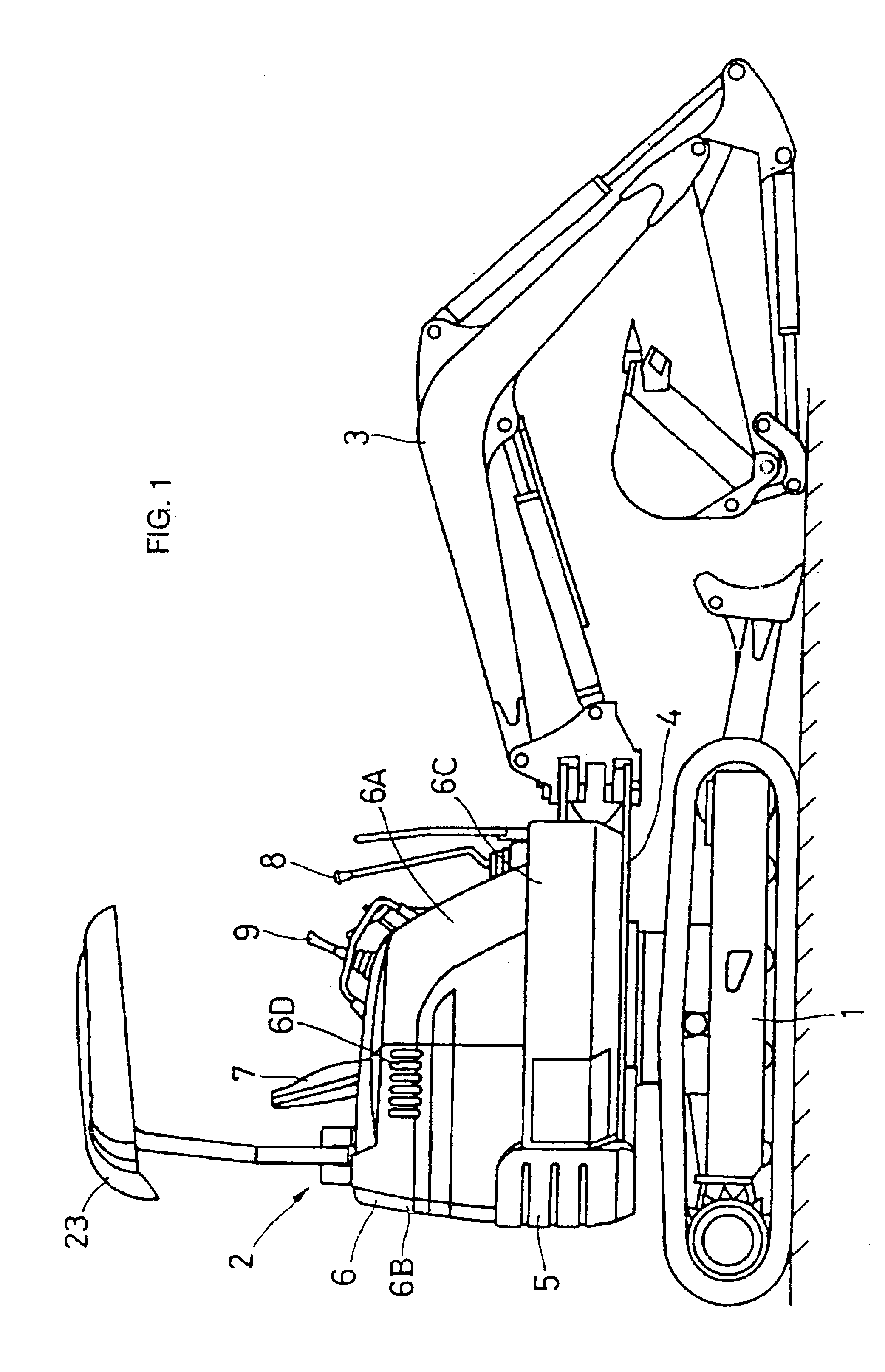
[0043]A first embodiment of a construction machine of the present invention will now be described with reference to FIG. 1-FIG. 6.
[0044]The hydraulic excavator of this embodiment has a lower traveling body 1 and an upper swiveling body 2 mounted on the undercarriage 1 so as to be capable of swiveling, and a boom 3 for carrying out excavation is provided at a front side of the upper swiveling body 2.
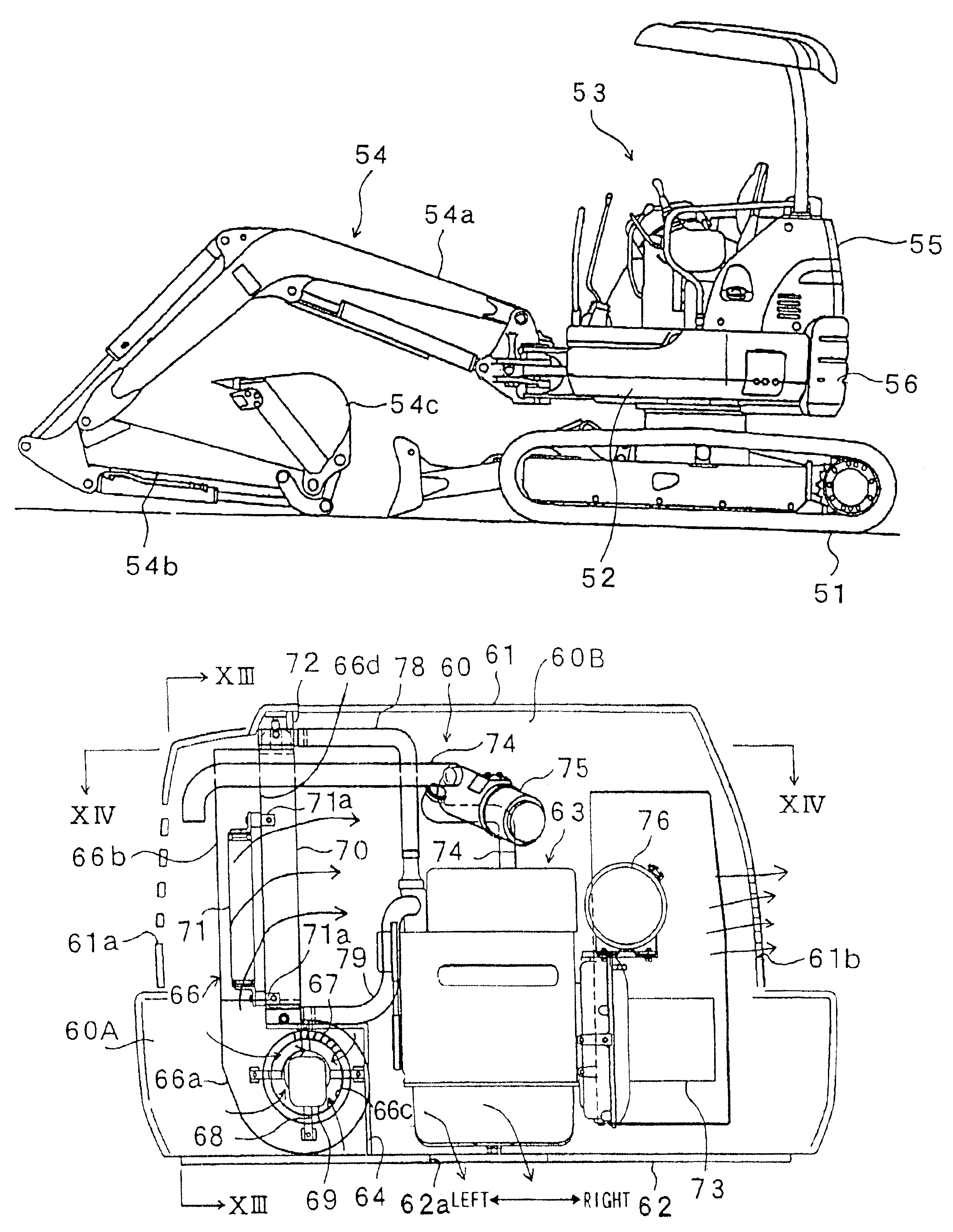
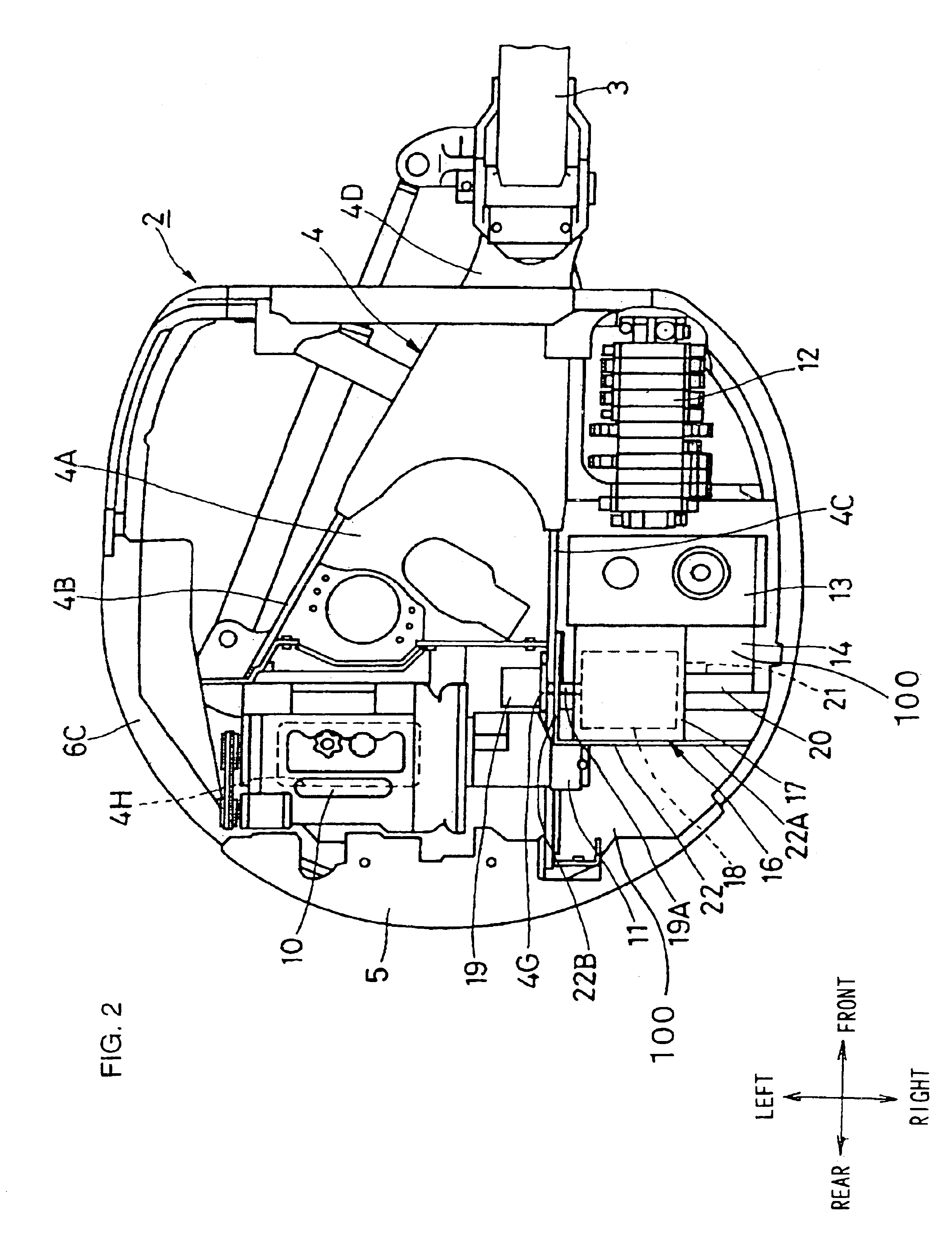
[0045]As shown in FIG. 1 and FIG. 2, the upper swiveling body 2 mainly comprises a swiveling frame 4, which will be described later, a driver's seat 7, an engine 10, a hydraulic pump 11, a control valve unit 12, a hydraulic fluid reservoir 13, a cooling air duct 14, a sirocco fan 16, a radiator 20 and an oil cooler 21, etc. The upper swiveling body 2 has a substantially circular shape overall when viewed from above.
[0046]As shown in FIG. 3 and FIG. 4, the swiveling frame 4 constituting a support structure for the turntable section 2 is mainly made up of a flat plate-shaped base plate 4A e...
second embodiment
[0085]A second embodiment of a construction machine of the present invention will now be described with reference to FIG. 7 and FIG. 8.
[0086]The second embodiment is characterized in that the hydraulic fluid reservoir has a side surface forming the cooling air passage as an inclined surface inclining in a direction towards the heat exchanger side, wherein heat dissipating fins are provided projecting from the side surface defining a cooling air passage for the hydraulic fuel tank. With the second embodiment, the same reference numerals are used for structural elements that are the same as those in the first embodiment described above, and description of those parts will be omitted.
[0087]As shown in FIG. 7 and FIG. 8, the hydraulic fluid reservoir 31 of the second embodiment is formed as a box-like container tightly closed by a front plate 31A, a rear plate 31B, a left side plate 31C, a right side plate 31D an upper plate 31E and a base plate 31F. A lower portion of the rear plate 31...
third embodiment
[0095]A third embodiment of a construction machine of the present invention will now be described with reference to FIG. 9.
[0096]The third embodiment is characterized in that the hydraulic fluid reservoir and the cooling air duct are provided in separate bodies. With the third embodiment, the same reference numerals are used for structural elements that are the same as those in the first embodiment described above, and description of those parts will be omitted.
[0097]The cooling air duct 41 of the third embodiment is provided adjacent to a rear side of the hydraulic fluid reservoir 13, and there is a slight gap between the cooling air duct 41 and the hydraulic fluid reservoir 13. Here, the cooling air duct 41 comprises a front plate 41A facing the rear plate 13B of the hydraulic fluid reservoir 13 with a slight gap between the front plate 41A and the rear plate 13B, a left side plate (not shown) extending from a left end of the front plate 41A towards the rear of the swiveling frame...
PUM
 Abstract
Description
Claims
Application Information