Motor-type power device

a power device and motor technology, applied in mechanical devices, transportation and packaging, gearing details, etc., can solve the problems of increased electric motor, insufficient oil, loss of driving force, etc., and achieve the effect of suppressing the stirring resistance of oil

Active Publication Date: 2009-05-21
HONDA MOTOR CO LTD
View PDF3 Cites 87 Cited by
  • Summary
  • Abstract
  • Description
  • Claims
  • Application Information

AI Technical Summary

Benefits of technology

[0011]The present invention was made in view of the aforementioned circumstances, and a first object of the present invention is to suppress the stirring resistance of oil to a minimum while ensuring lubricating performance by retaining an appropriate oil level in a transmission housing chamber and an electric motor housing chamber of a motor-type power device.

Problems solved by technology

However, when the quantity of oil that is held in the electric motor housing chamber and the transmission housing chamber is too large, there is the problem that a resistance to stirring of the oil by the differential gear or rotor of the electric motor increases and a loss in the driving force occurs.
Conversely, if the quantity of oil is too small, when the oil in the transmission housing chamber moves to the electric motor housing chamber through the oil communication passage or the oil in the electric motor housing chamber moves to the transmission housing chamber through the oil communication passage due to a centrifugal force accompanying turning of the vehicle, there is the possibility that oil will be insufficient and a lubrication failure will occur.
In particular, heretofore when oil of a transmission housing chamber that has a relatively small volume capacity moves to an electric motor housing chamber that has a relatively large volume capacity, there has been the problem that the oil in the transmission housing chamber is insufficient and a lubrication failure occurs at a differential gear or the like, and furthermore there is excess oil in the electric motor housing chamber and the stirring resistance of the oil with respect to the rotor of the electric motor increases.
Moreover, in the above described conventional device, since a resolver is disposed between the left side surface of the electric motor and a partitioning wall that separates the electric motor housing chamber and the transmission housing chamber, there has been the problem that it is necessary to disassemble all of the motor-type power device in order to perform maintenance or replacement of the resolver, and that work requires much time and labor.
However, when this kind of configuration is adopted, it is necessary to supply oil to the bearing that supports the right end of the rotor shaft and the bearing that supports the right end of the center shaft for lubrication, and there is the problem that if a large quantity of the oil flows into the electric motor housing chamber the resistance to stirring of the oil by the rotor of the electric motor will increase.
Moreover, in the above described conventional motor-type power device, since lubrication of the differential gear, the reduction gear, and the electric motor are performed with oil that is scooped up by the final driven gear, not only is it difficult to uniformly distribute oil to parts to be lubricated that exist around various portions of the motor-type power device, but there is also the problem that the stirring resistance of the oil at the time of scooping up the oil with the final driven gear is extremely large and causes an energy loss.
Further, since it is necessary to secure a storage chamber to store oil that is scooped up, there is the problem that this leads to an increase in the volume capacity and weight of the case.

Method used


Image

  • Motor-type power device
  • Motor-type power device
  • Motor-type power device

Examples


first embodiment

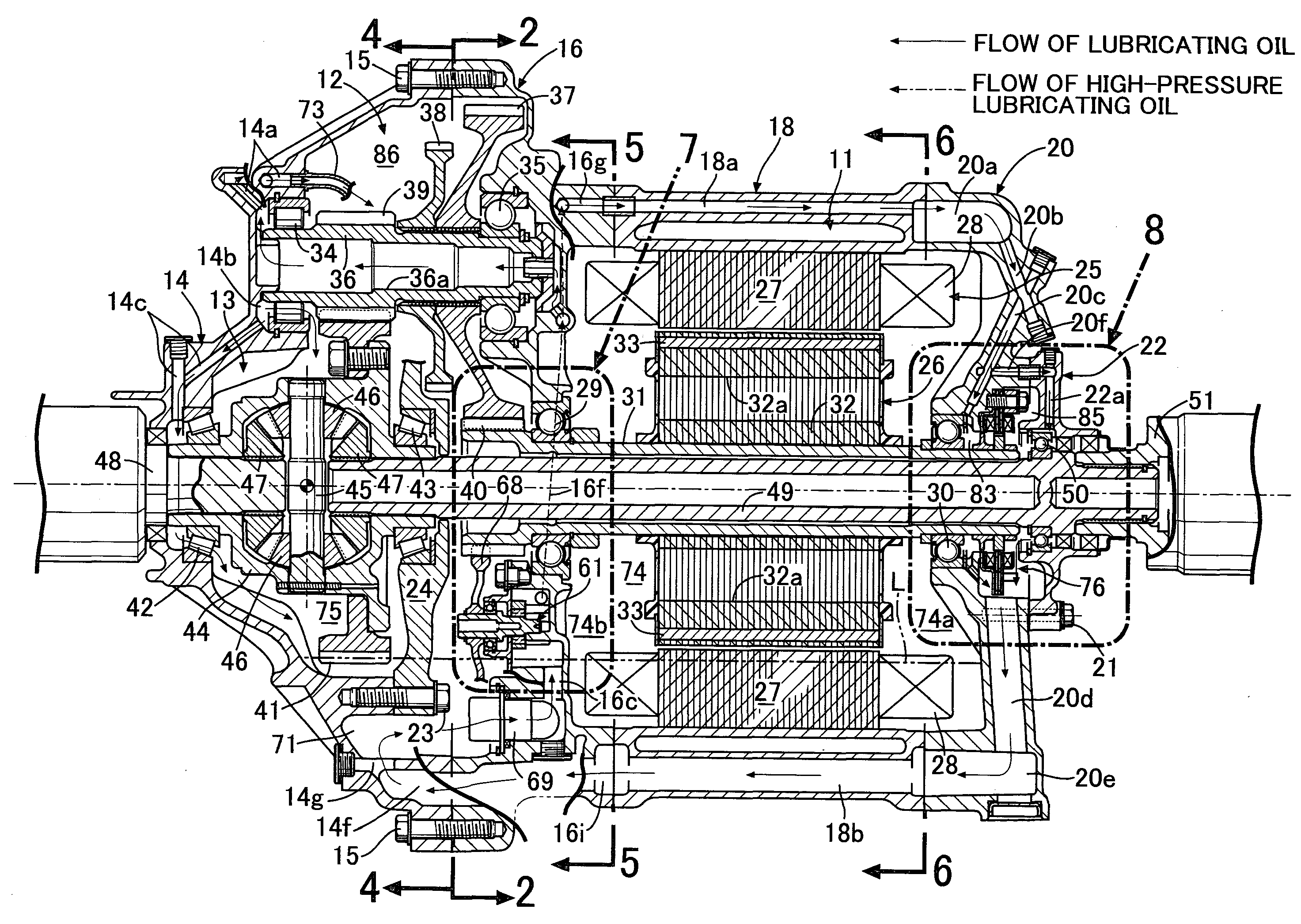
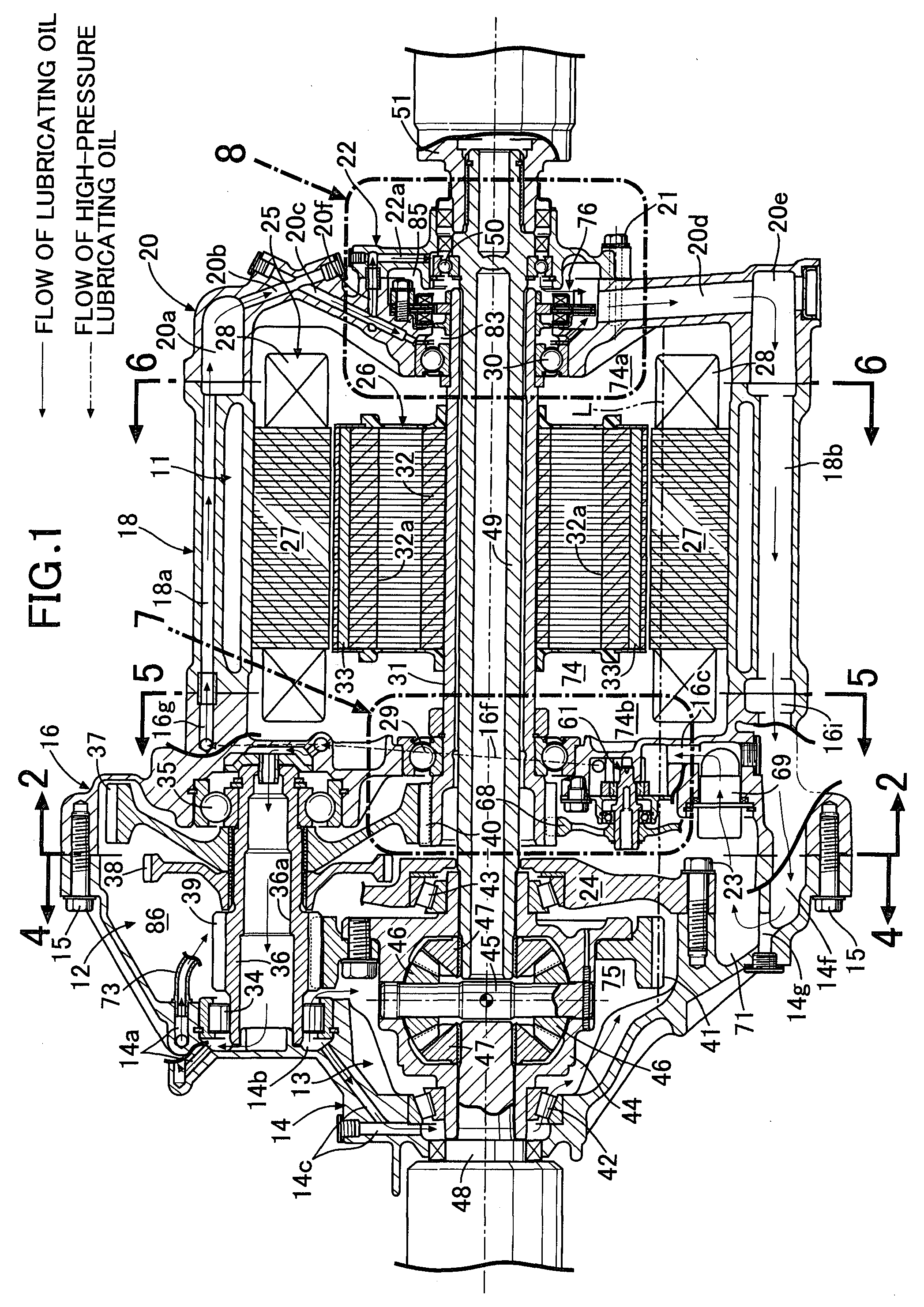
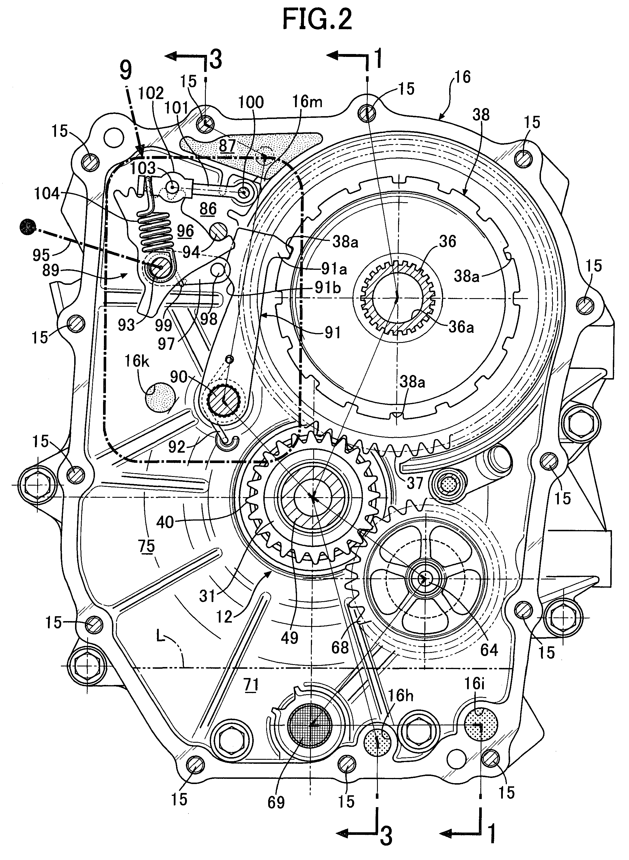
[0049]Hereunder, the present invention is described based on FIG. 1 to FIG. 14.

[0050]As shown in FIG. 1 and FIG. 3, a motor-type power device that is used as a power unit of an electric automobile integrally comprises an electric motor 11, a reduction gear 12, and a differential gear 13. The contour thereof comprises a transmission case 14 that is located at the left end in the vehicle width direction, a motor / transmission case 16 that is joined by bolts 15 to the right end of the transmission case 14, a motor center case 18 that is joined by bolts 17 to the right end of the motor / transmission case 16, a motor side case 20 that is joined by bolts 19 to the right end of the motor center case 18, a center shaft bearing support 22 that is joined by bolts 21 to the right end of the motor side case 20, and an intermediate case 24 that is joined by bolts 23 to the inner surface of the transmission case 14. The electric motor 11 is housed within the motor / transmission case 16, the motor ce...


PUM


Abstract

Due to a centrifugal force in a vehicle width direction due to turning of an automobile, oil in an electric motor housing chamber housing an electric motor and oil in a transmission housing chamber housing a reduction gear and a differential gear flows to-and-fro via oil communication passages that penetrate a partitioning wall. An opening on the transmission housing chamber side of the oil communication passages is spaced from the partitioning wall. Hence, when oil moves from the transmission housing chamber side to the electric motor housing chamber side, it is possible to prevent the oil quantity on the electric motor housing chamber side from increasing excessively and suppress an increase in resistance to oil stirring by a rotor of the electric motor while retaining a constant oil amount on the transmission housing chamber side to ensure lubricating performance for the reduction gear and the differential gear.

Description

TECHNICAL FIELD[0001]The present invention relates to a motor-type power device, in which rotation of a rotor shaft of an electric motor is transmitted to a differential gear via a reduction gear, and one output shaft of a pair of output shafts of the differential gear is disposed inside the rotor shaft.BACKGROUND OF THE INVENTION[0002]Such a motor-type power device is disclosed in Japanese Patent Application Laid-Open No. 2005-278319. In that motor-type power device, an electric motor housing chamber on a right side in the vehicle width direction and a transmission housing chamber on a left side in the vehicle width direction are defined by a partitioning wall, and the configuration is such that oil that is supplied to the electric motor housing chamber and the transmission housing chamber from an oil pump driven by an electric motor can flow back and forth between the two housing chambers via an oil communication passage that penetrates through a lower portion of the partitioning ...

Claims


Application Information

Patent Timeline
Patent Type & Authority Applications(United States)
IPC IPC(8): H02K7/08H02K7/116F16H57/02F16H57/037F16H57/038F16H57/039F16H57/04
CPCB60K17/12F16H57/0443H02K2205/09H02K7/116H02K9/19F16H57/0476
Inventor MOGI, SEIICHI
Owner HONDA MOTOR CO LTD
Why Eureka
Try Eureka