
Tubular centrifuge and method thereof for keeping balance of rotating drum

A tubular centrifuge and drum technology, applied in centrifuges, centrifuges with rotating drums, etc., can solve the problems of drum wear, rotation axis deviating from the vertical position, and inability to separate materials, to avoid rotating drums. Drum imbalance, optimized centrifugation effect, improved residence time effect

Inactive Publication Date: 2016-04-27
SHANGHAI DAIBAO MACHINERY EQUIP CO LTD
View PDF12 Cites 5 Cited by
  • Summary
  • Abstract
  • Description
  • Claims
  • Application Information

AI Technical Summary

Problems solved by technology

[0002] Tubular centrifuges are usually used in the centrifugation process of materials in food and pharmaceutical industries. During use, due to uneven distribution of materials in the drum or other reasons, the rotation axis of the drum will often deviate from the vertical position, resulting in The drum cannot effectively separate the materials, and may even cause damage to the tube centrifuge
[0003] The tubular centrifuges on the market use a bearing device at one end of the drum to prevent the rotation axis of the drum from deviating from the vertical position, so that the drum can be kept in balance during the rotation process, but this method will cause The wear of the drum, on the other hand, the bearing device itself needs to be equipped with a lubrication device, and grease pollution often occurs during the lubrication process. At the same time, this leads to a cumbersome structure and complicated installation of the tubular centrifuge, and the bearing device needs to be replaced frequently. Cost of production

Method used


Image

  • Tubular centrifuge and method thereof for keeping balance of rotating drum
  • Tubular centrifuge and method thereof for keeping balance of rotating drum
  • Tubular centrifuge and method thereof for keeping balance of rotating drum

Examples


Embodiment 1

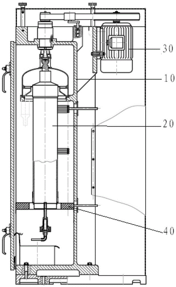
[0039] Such as figure 1 As shown, Embodiment 1 discloses a tubular centrifuge, including a frame 10, a drum 20 and a driving device 30, the driving device 30 is arranged on the frame 10, and the driving device 30 is connected with the drum 20 for driving The drum 20 rotates itself in the vertical direction around the axis of the drum.

[0040] The tube centrifuge also includes: an induction device, which is used to monitor whether the rotation axis of the drum deviates from the vertical direction, and generates a drum position signal when the rotation axis of the drum is detected to deviate from the vertical direction; magnetic reset The device 40, the magnetic resetting device 40 is fixed on the frame 10 and connected with the drum 20, the magnetic resetting device 40 is also connected with the induction device and receives the drum position signal. When the sensing device detects that the rotation axis of the drum deviates from the vertical direction, the magnetic resetting...

Embodiment 2

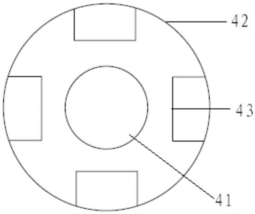
[0043] Such as figure 2 As shown, the difference between the second embodiment and the first embodiment is that the magnetic reset device 40 in the tubular centrifuge disclosed in the second embodiment includes: a magnetic rotor 41, the magnetic rotor 41 is arranged on the drum and is connected with the drum Coaxial arrangement; a stator disk 42, the stator disk 42 is fixed on the frame, the stator disk 42 and the magnetic rotor 41 are coaxially arranged, and there is a gap between the stator disk 42 and the magnetic rotor 41, and the stator disk 42 is provided with four Winding 43, and the four windings 43 are evenly distributed on the stator plate 42; a control device, the control device is connected with the induction device and receives the drum position signal sent by the induction device, and the control device is connected to the four windings 43 respectively.

[0044] When the induction device senses that the rotation axis of the drum deviates from the vertical direct...

Embodiment 3

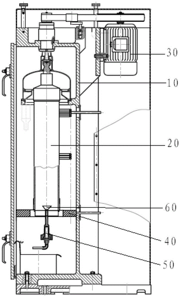
[0048] The difference between Embodiment 3 and Embodiment 1 is that the tubular centrifuge disclosed in Embodiment 3 also includes: an alarm device, which is connected to the sensing device; When all segments deviate from the vertical direction, the alarm device sends out a first alarm signal; when the sensing device senses that the angle of rotation axis of the drum deviates from the vertical direction is greater than the first angle, the alarm device sends out a second alarm signal.

[0049] When within the first period of time, the drum does not restore balance under the action of the magnetic reset device, then the operator can take countermeasures in time according to the first alarm signal, such as emergency shutdown, replacement of the magnetic rotor or repair of the unbalanced drum Manual reset, etc. When the angle of rotation axis of the drum deviates from the vertical direction is greater than the first angle, the magnetic reset device can no longer restore the balan...


PUM


Abstract

The invention discloses a tubular centrifuge and a method thereof for keeping balance of a rotating drum. The tubular centrifuge comprises a frame, the rotating drum and a driving device; the driving device is arranged on the frame, is connected with the rotating drum, and is used for driving the rotating drum to rotate around the axis of the rotating drum in the vertical direction; an induction device is used for monitoring if the rotating axis of the rotating drum is deviated from the vertical direction and generating a rotating drum position signal when monitoring that the rotating axis of the rotating drum is deviated from the vertical direction; and a magnetic return device is fixed on the frame, is connected with the rotating drum, is connected with the induction device, receives the rotating drum position signal, and drives the rotating drum to enable the rotating axis of the rotating drum to return to the vertical direction according to the rotating drum position signal. The tubular centrifuge can effectively guarantee the rotating axis of the rotating drum to be always in the vertical direction, enables the rotating drum to keep the balance state, and effectively guarantees stable operation.

Description

technical field [0001] The invention relates to the structural design field of a tubular centrifuge, in particular to a tubular centrifuge and a method for maintaining the balance of a drum. Background technique [0002] Tubular centrifuges are usually used in the centrifugation process of materials in food and pharmaceutical industries. During use, due to uneven distribution of materials in the drum or other reasons, the rotation axis of the drum will often deviate from the vertical position, resulting in The drum cannot effectively separate the materials, and may even cause damage to the tube centrifuge. [0003] The tubular centrifuges on the market use a bearing device at one end of the drum to prevent the rotation axis of the drum from deviating from the vertical position, so that the drum can be kept in balance during the rotation process, but this method will cause The wear of the drum, on the other hand, the bearing device itself needs to be equipped with a lubricat...

Claims


Application Information

Patent Timeline
IPC IPC(8): B04B9/14B04B1/00B04B11/00B04B13/00B04B15/00
CPCB04B9/14B04B1/00B04B9/146B04B11/00B04B13/00B04B15/00
Inventor 黄磊
Owner SHANGHAI DAIBAO MACHINERY EQUIP CO LTD
Learn More