
Quasi-zero stiffness coupling

A quasi-zero stiffness, coupling technology, applied in rigid shaft couplings, couplings, springs/shock absorbers, etc., can solve problems such as complex structure, large size, difficulty in miniaturization, precision, etc., to achieve Compact structure, reduced torsional vibration level, and miniaturization

Inactive Publication Date: 2016-04-27
XI AN JIAOTONG UNIV
View PDF12 Cites 10 Cited by
  • Summary
  • Abstract
  • Description
  • Claims
  • Application Information

AI Technical Summary

Problems solved by technology

After searching, only the patent "torsional quasi-zero stiffness vibration isolator (application number: 201410558315.8)" proposed a quasi-zero stiffness vibration isolator in the torsional direction, but the disadvantage of this method is that the structure is complex, the size is large, and it is difficult to miniaturize , precision

Method used


Image

  • Quasi-zero stiffness coupling
  • Quasi-zero stiffness coupling
  • Quasi-zero stiffness coupling

Examples


Embodiment Construction

[0023] The present invention will be described in further detail below in combination with specific embodiments.

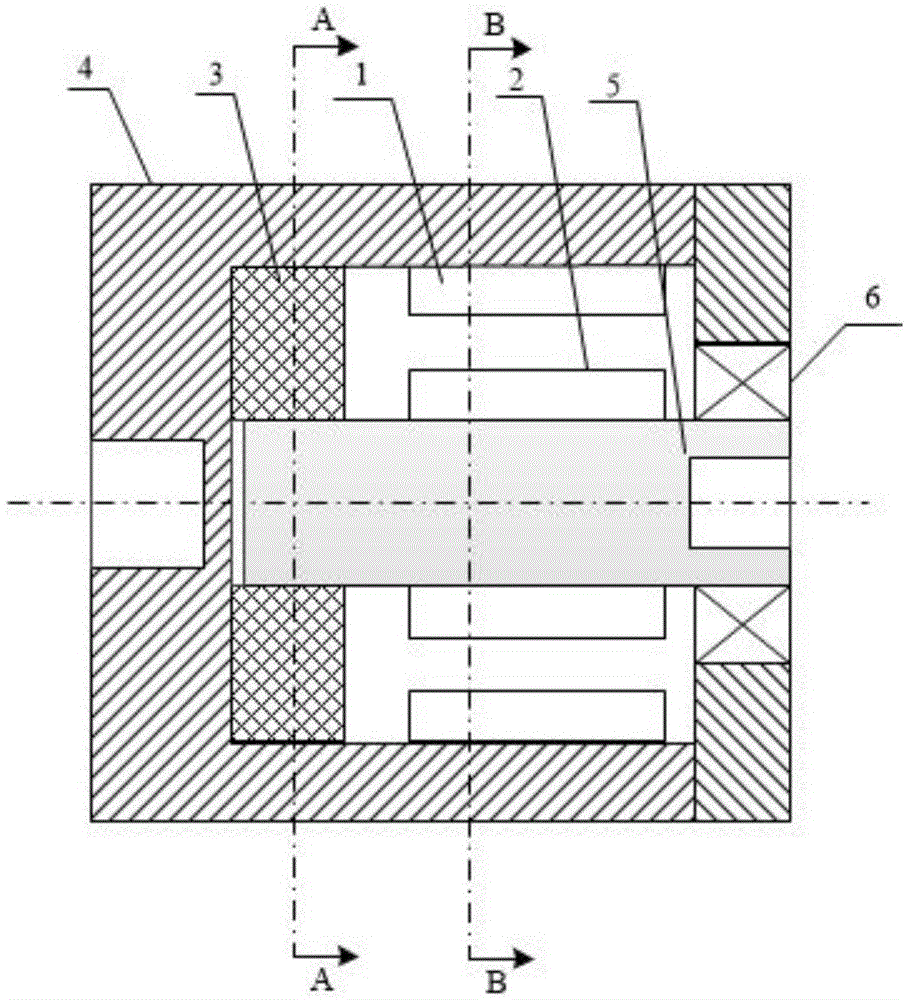
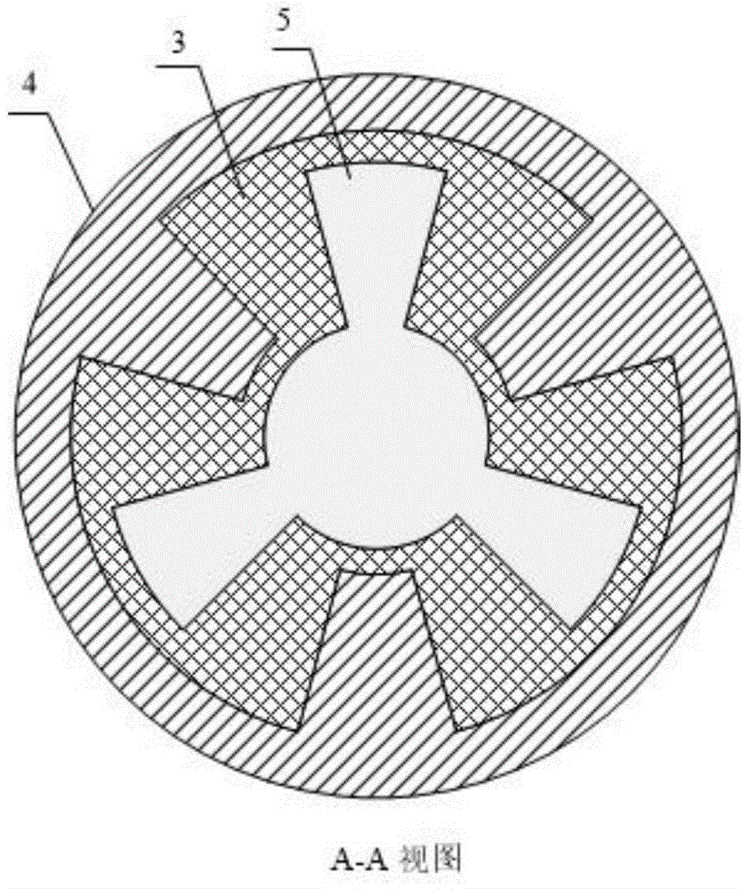
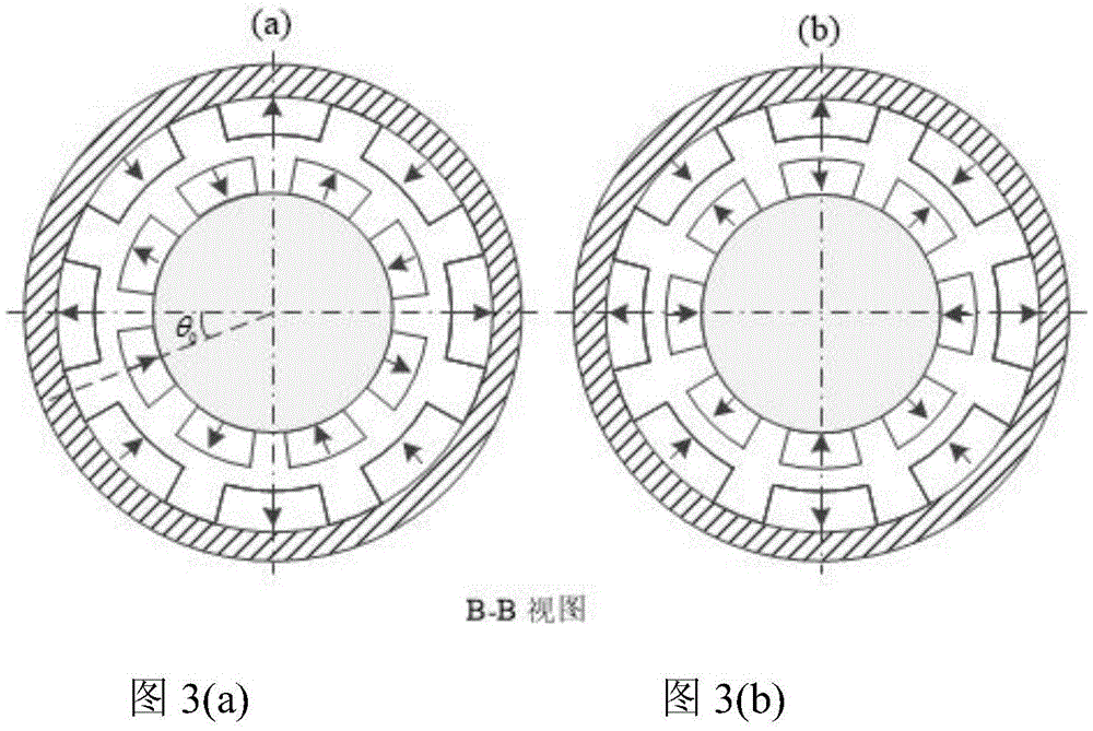
[0024] Such as figure 1 As shown, a quasi-zero stiffness coupling of the present invention includes an outer magnetic ring 1 , an inner magnetic ring 2 , a rubber spring 3 , a housing 4 , an inner shaft 5 and a bearing 6 . The outer magnetic ring 1 can be fixed on the shell 4 and the inner magnetic ring 2 can be fixed on the inner shaft 5 by designing a suitable clamp. The structure of the outer magnetic ring 1 and the inner magnetic ring 2 is as follows image 3 As shown, they are all composed of several magnetic tiles, and the number of magnetic tiles is the same. The magnetization direction of the magnetic tile is along the radial direction and changes alternately. When the outer magnetic ring 1 and the inner magnetic ring 2 are in image 3 In the relative position shown in (b), the magnetic moment generated by the magnetic spring composed of them is zero, ...


PUM


Abstract

A quasi-zero stiffness coupling comprises a shell and an inner shaft arranged in the shell. One end of the inner shaft is connected with the bottom of the shell through a rubber spring, and the rubber spring is a tooth-type rubber spring. The inner ring of the rubber spring and teeth at the end of the inner shaft are clamped to each other closely, and the outer ring of the rubber spring and teeth on the inner wall of the shell are clamped to each other closely, so that it is guaranteed that the shell drives the inner shaft to rotate together when twisting. An outer magnetic ring is fixed to the inner wall of the shell, an inner magnetic ring is fixed to the outer circumferential ring of the inner shaft, and the outer magnetic ring and the inner magnetic ring constitute a magnetic spring. The outer ring of the bearing is matched with the shell, the inner ring of the bearing and the inner shaft are matched to restrain the inner shaft from making axial movement and radial movement relative to the shell. The negative stiffness of the outer magnetic ring and the inner magnetic ring are made approximate to the positive stiffness of the rubber spring by selecting geometrical parameters of the outer magnetic ring and the inner magnetic ring, so that the total stiffness is made to reach a quasi-zero state. The quasi-zero stiffness coupling can effectively transmit driving torque, also can isolate disturbance torque, has a wide vibration isolation frequency band, and has a good isolation effect on low-frequency disturbance. The quasi-zero stiffness coupling can be used for solving the torsional vibration problem of a rotor system, and is particularly suitable for precise rotor systems.

Description

technical field [0001] The invention relates to a shaft coupling, in particular to a quasi-zero-stiffness coupling capable of effectively transmitting driving torque and having a low-frequency vibration isolation effect, which can well suppress torsional vibration of a shaft system. Background technique [0002] The phenomenon of torsional vibration commonly exists in automobiles, ships, aerospace and other fields, and basically all rotor systems have torsional vibration problems. Torsional vibration will cause gear wear and shaft fracture, which will affect the normal operation of mechanical equipment; severe torsional vibration will also cause noise problems, especially for engines on aircraft and ships. The strong noise caused by torsional vibration will seriously affect stealth Effect; for precision engineering fields, such as spacecraft systems, torsional vibration will affect the accuracy of precision instruments. [0003] The coupling is an essential part of the roto...

Claims


Application Information

Patent Timeline
IPC IPC(8): F16D1/02F16F15/127
CPCF16D1/02F16F15/127
Inventor 郑宜生路广霖张希农罗亚军张亚红谢石林
Owner XI AN JIAOTONG UNIV
Learn More