Supercharge Your Innovation With Domain-Expert AI Agents!

Dynamic calibration method for springs

A dynamic calibration and pending calibration technology, which is applied in the testing of measuring devices, instruments, and mechanical components, can solve the problems of inability to fully reflect the working characteristics of springs, few calibration measurement points, and low precision.

Active Publication Date: 2016-04-27
BEIJING MECHANICAL EQUIP INST
View PDF6 Cites 1 Cited by
  • Summary
  • Abstract
  • Description
  • Claims
  • Application Information

AI Technical Summary

Problems solved by technology

[0003] The purpose of the present invention is to provide a spring dynamic calibration method to solve the problems of low accuracy, few calibration measurement points and inability to fully reflect the working characteristics of the spring in the entire range and at different operating frequencies in the current manual static calibration.

Method used


Image

  • Dynamic calibration method for springs

Examples


Embodiment Construction

[0023] A kind of spring dynamic calibration method, its concrete steps are:

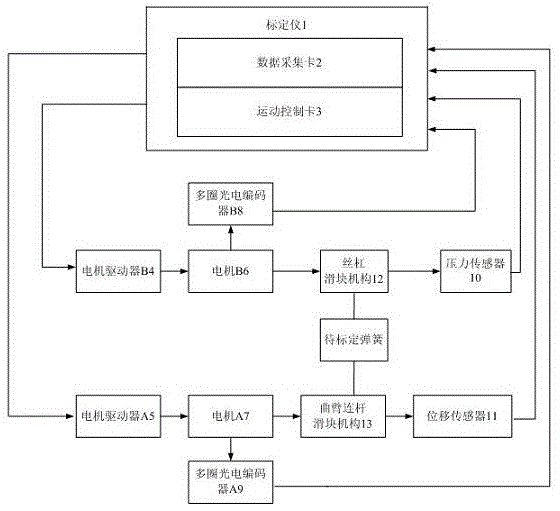
[0024] The first step is to build a spring dynamic calibration system

[0025] Spring dynamic calibration system, including: calibration instrument 1, motor driver A5, motor A7, multi-turn photoelectric encoder A9, motor driver B4, motor B6, multi-turn photoelectric encoder B8, crank arm linkage slider mechanism 13, lead screw Slider mechanism 12 , displacement sensor 11 and pressure sensor 10 ; wherein, calibration instrument 1 includes: data acquisition card 2 and motion control card 3 . The output end of the calibration instrument 1 is respectively connected with the input end of the motor driver A5 and the input end of the motor driver B4 through cables; The block mechanism 13 and the multi-turn photoelectric encoder A9 are connected through a rotating shaft, and the output end of the crank arm linkage slider mechanism 13 is connected with the input end of the displacement sensor 11 through a ca...


PUM


Abstract

The invention provides a dynamic calibration method for springs. The method comprises following steps: a dynamic calibration system for springs is built which comprises a calibration device (1), a motor driver A (5), a motor A (7), a motor driver B (4), a motor B (6), a crank arm connecting rod slide block mechanism (13), a lead screw slide block mechanism (12), a displacement sensor (11) and a pressure sensor (10); a spring to be calibrated is pre-tightened to an initial position by the lead screw slide block mechanism (12); a working stroke of the spring to be calibrated is set by the crank arm connecting rod slide block mechanism (13); a working frequency of the spring to be calibrated is set by a motion control card (3); pressure data is generated by the pressure sensor (10) and displacement data is generated by the displacement sensor (11); the pressure data and the displacement data are collected by the calibration device (1); and performance indexes of the spring to be calibrated are obtained by the calibration device (1). The calibration method has high automation degree, high calibration precision, and flexible and convenient applications.

Description

technical field [0001] The invention relates to a spring calibration method, in particular to a spring dynamic calibration method. Background technique [0002] At present, most of the spring calibration methods use manual static calibration. The spring force and displacement values ​​of the pressure sensor are read by manual compression of the spring by the tooling, and the data of multiple points are recorded to obtain the calibration curve of the spring force and displacement. The manual static calibration method has large errors and few calibration measurement points. It cannot be dynamically calibrated for springs at different operating frequencies, and cannot fully reflect the working characteristics of the springs in the entire range and at different operating frequencies. Contents of the invention [0003] The purpose of the present invention is to provide a spring dynamic calibration method to solve the problems of low accuracy, few calibration measurement points ...

Claims


Application Information

Patent Timeline
Patent Type & Authority Applications(China)
IPC IPC(8): G01M13/00
CPCG01M13/00
Inventor 高润鹏尚焜胡源渊何成峰王鹏飞
Owner BEIJING MECHANICAL EQUIP INST
Features
  • R&D
  • Intellectual Property
  • Life Sciences
  • Materials
  • Tech Scout
  • Unparalleled Data Quality
  • Higher Quality Content
  • 60% Fewer Hallucinations
Learn More