Charging system

A charging system and charging detection technology, applied in the direction of collectors, electric vehicles, electrical components, etc., can solve the problems of inconvenient portability, wrong charging of battery packs, loss of users, etc., and achieve the effect of simple and convenient operation.

Active Publication Date: 2016-04-27
NANJING CHERVON IND
View PDF5 Cites 30 Cited by
  • Summary
  • Abstract
  • Description
  • Claims
  • Application Information

AI Technical Summary

Problems solved by technology

In this way, for users, different chargers need to be purchased for different battery packs, and it is very inconvenient to carry. In addition, it may also cause the battery pack to be inserted into the wrong charger. If there is no corresponding identification and protection in the charging device system, similar misoperations will cause damage to the battery pack and bring unnecessary losses to users

Method used


Image

  • Charging system
  • Charging system
  • Charging system

Examples


Embodiment Construction

[0034] The specific implementation manner of the present invention will be further described below in conjunction with the accompanying drawings.

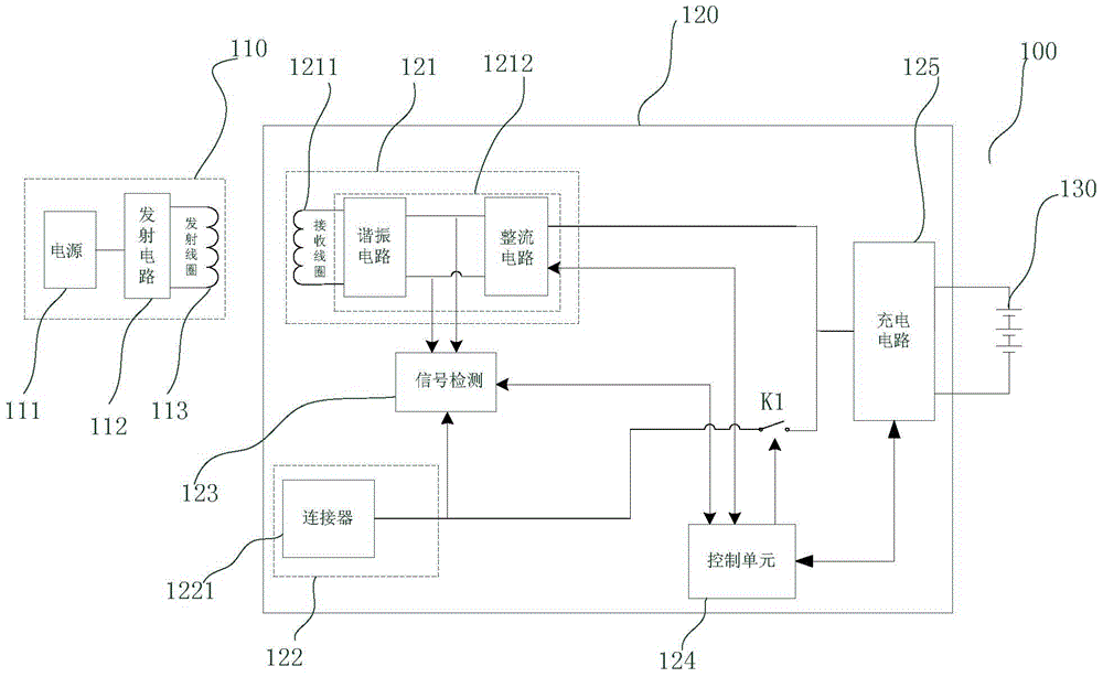
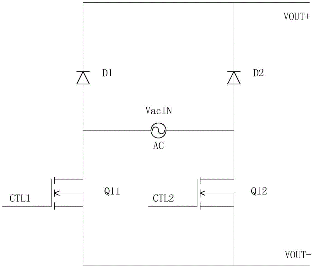
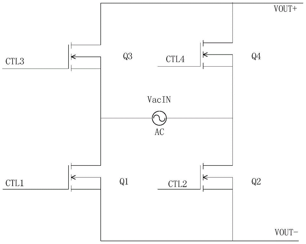
[0035] see Figure 1 to Figure 3 , figure 1 It is a circuit schematic diagram of the charging system 100 according to the first embodiment of the present invention. The mark 110 in the figure represents a wireless power transmitting device. Those skilled in the art can easily understand that the wireless power transmitting device includes a power supply 111, a transmitting circuit 112 and a transmitting coil 113. Specifically, the wireless transmitting coil 111 is electrically connected to the transmitting circuit 112. The power supply here generally refers to the AC power supply. After being connected to the AC power supply, the AC power supply is converted into a DC power supply by the AC-DC module (not shown) of the transmitting circuit to supply power for other modules in the circuit. It should be understood that wireless cha...


PUM


Abstract

The invention provides a charging system. The charging system comprises a wireless power emission device, an adapter, a wireless power source access unit, a wired power source access unit, a signal detection module, a charging detection circuit and a control unit, wherein the control unit is used for managing electric power channels according to an access state of a wired power source or a wireless power source detected by the signal detection module, the control unit further comprises a cell monitoring module, and the controller utilizes the cell monitoring module to acquire cell parameters from the charging detection circuit and controls electric power output of the wireless power emission device or the adapter to provide proper electric power for chargeable cells. The charging system has the automatic adjustment function, when wireless electric access is employed, output power is adjusted according to demand change of the output power of the wireless power source access unit; when wired electric access is employed, carrying all types of chargers for charging the cells is not required, and operation is simple and convenient.

Description

technical field [0001] The invention relates to the charging field, in particular to a charging system with an automatic adjustment function. Background technique [0002] Existing electric tools powered by battery packs are mainly charged through chargers with wired interfaces or power connectors, while battery packs are used due to their limited battery life and need to be frequently replaced or charged in time. In many areas, due to the limitations of the environment or usage scenarios, there is no power interface, and the battery pack cannot be charged in time, so it cannot guarantee the needs of working in special environments and for a long time. [0003] On the other hand, since the chemical substances of the battery elements in various battery packs and the nominal voltage of the battery packs are different, it is often necessary to match different charging devices. In this way, for users, different chargers need to be purchased for different battery packs, and it i...

Claims


Application Information

Patent Timeline
Patent Type & Authority Applications(China)
IPC IPC(8): H02J7/10
Inventor 董爱香
Owner NANJING CHERVON IND
Why Eureka
Try Eureka