
Cloud scheduling system, method and device for removing tight coupling of use case and environment

A tightly coupled, use-case technology, applied in the field of telecom automation testing, can solve the problems of poor portability, limit the flexibility and operability of equipment automation testing, and achieve the effect of improving portability

Inactive Publication Date: 2016-04-27
ZTE CORP
View PDF5 Cites 5 Cited by
  • Summary
  • Abstract
  • Description
  • Claims
  • Application Information

AI Technical Summary

Problems solved by technology

Moreover, the environmental data used in the use case is also strongly coupled with the specific environment. For example, if the specific physical networking information such as the slot where the board is located and the IP address of the board changes, the tester must modify the use case and re-debug it once.
Therefore, the portability of use cases is poor, limiting the flexibility and operability of device automation testing

Method used


Image

  • Cloud scheduling system, method and device for removing tight coupling of use case and environment
  • Cloud scheduling system, method and device for removing tight coupling of use case and environment
  • Cloud scheduling system, method and device for removing tight coupling of use case and environment

Examples


Embodiment 1

[0087] The trigger condition of this embodiment is a periodic trigger, based on Figure 5 The system implementation shown, as Figure 6 As shown, the specific implementation steps are as follows:

[0088] Step 601: The environment agent sends a mounting request to the cloud dispatching center, and the cloud dispatching center responds that the mounting is successful;

[0089] Step 602: The cloud dispatching center periodically scans the test tasks, and when the time reaches 2 o'clock every day, it triggers the test task 1 to run, and puts the test case 1 into the waiting queue;

[0090] Step 603: Both test environment 1 and test environment 2 will request use cases from the cloud dispatching center through the environment agent when they are idle;

[0091] It should be noted that the test environment is idle when no test cases are running.

[0092] Step 604: When the cloud scheduling center receives the use case request from the environment agent, it will match the resource...

Embodiment 2

[0101] The trigger condition of this embodiment is instant trigger, also based on Figure 5 The system implementation shown, as Figure 7 As shown, the specific implementation steps are as follows:

[0102] Step 701: The environment agent sends a mounting request to the cloud dispatching center, and the cloud dispatching center responds that the mounting is successful;

[0103] Step 702: The cloud scheduling center periodically scans the test task. If someone merges the code into the version management library of the cloud scheduling system, the continuous integration automatically generates a new version of the specification package and puts it in the designated directory of the FTP server, triggering The above test task 2 runs, and puts test case 2 into the waiting queue;

[0104] Step 703: Both test environment 1 and test environment 2 will request use cases from the cloud dispatching center through the environment agent when they are idle;

[0105] Step 704: When the cl...


PUM


Abstract

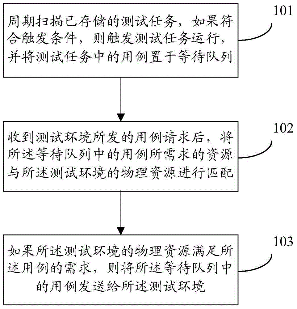
The invention discloses a method for removing tight coupling of a use case and an environment. The method comprises the steps of: scanning a stored test task periodically, triggering the test task to run if a trigger condition is met, and placing the use case of the test task in a waiting queue; and matching resources required by the use case in the waiting queue with physical resources of the test environment when a use case request sent by the test environment is received, and sending the use case in the waiting queue to the test environment if the physical resources of the test environment meet requirement of the use case. The invention further discloses a device for implementing the method and a cloud scheduling system at the same time.

Description

technical field [0001] The invention relates to the telecommunications automation testing technology in the communication field, in particular to a method, device and cloud scheduling system for decoupling use cases and environments. Background technique [0002] In the automated testing technology of telecommunication equipment, the system test cases and the specific tested environment are usually tightly coupled. Moreover, due to the wide variety of telecommunications equipment, its networking scenarios are even more complex, and some networking scenarios even include more than 10 types of telecommunications equipment. When a tester writes a test case, he has already determined which environment the use case will run on, which has strong pertinence. If the environment configuration changes later, the original use case needs to be modified according to the new configuration. Moreover, the environmental data used in the use case is also strongly coupled with the specific e...

Claims


Application Information

Patent Timeline
IPC IPC(8): H04L12/26H04L29/08
Inventor 刘娜欧林宝
Owner ZTE CORP
Learn More