Supercharge Your Innovation With Domain-Expert AI Agents!

Industrial vehicle

A technology for operating vehicles and operating volume, which is applied in the directions of transmission control, electrical control, belt/chain/gear, etc., and can solve problems such as vehicle shaking

Active Publication Date: 2016-04-27
HITACHI CONSTRUCTION MACHINERY CO LTD
View PDF5 Cites 0 Cited by
  • Summary
  • Abstract
  • Description
  • Claims
  • Application Information

AI Technical Summary

Problems solved by technology

[0002] In a work vehicle equipped with an HST travel drive device in which a hydraulic motor is connected to a hydraulic pump in a closed circuit, the hydraulic pump is directly connected to the engine, and the movement of the vehicle is easily affected by changes in the engine rotational speed, so the vehicle as a whole tends to be displaced in the front-rear direction. wobbly swing

Method used


Image

  • Industrial vehicle
  • Industrial vehicle
  • Industrial vehicle

Examples


no. 1 approach

[0106] According to the first embodiment described above, the following effects can be obtained.

[0107] (1) When the required engine rotational speed Nr is greater than the predetermined value N0, the acceleration Ra of the required engine rotational speed Nr based on the difference between the required engine rotational speed Nr and the actual engine rotational speed Na, in other words, per unit time (for example, 10 ms) Increase the rotation speed to perform calculations. Thereby, it is possible to suppress the jumping-out phenomenon at the time of starting and the occurrence of hunting, so that the transition from deceleration to acceleration can be performed quickly, that is, the traction force can be rapidly increased. Since the ride comfort of the vehicle can be improved, the burden on the operator can be reduced. In addition, it is also possible to improve work efficiency.

[0108] (2) When the accelerator pedal 192 is depressed and operated, when the actual engine ...

Deformed example 1

[0114] In the above-described embodiment, the acceleration and deceleration of the requested engine rotational speed Nr are calculated based on the difference between the requested engine rotational speed Nr and the actual engine rotational speed Na, but the present invention is not limited thereto. The present invention can be configured to calculate only the acceleration of the requested engine rotational speed Nr.

Deformed example 2

[0116] In the above-mentioned embodiment, when the accelerator pedal 192 is depressed and operated, the acceleration Ra (hereinafter referred to as Ra1 ) at which the required engine rotational speed Nr is equal to or less than the predetermined value N0 and the required engine rotational speed Nr are set to be greater than the predetermined value N0 Also, the acceleration Ra (hereinafter referred to as Ra2) when the value obtained by subtracting the required engine speed Nr from the actual engine speed Na is greater than the threshold N1 is Rah, but the present invention is not limited thereto. The acceleration Ra1 and the acceleration Ra2 can be set to different values ​​from each other.

[0117] In the above-described embodiment, when the accelerator pedal 192 is reset, the deceleration Rd (hereinafter, referred to as Rd1 ) when the required engine rotational speed Nr is equal to or less than the predetermined value N0 is set at a predetermined ratio to the required engine r...


PUM


Abstract

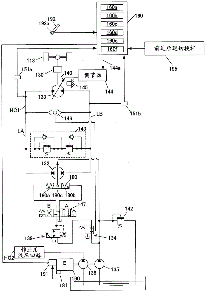
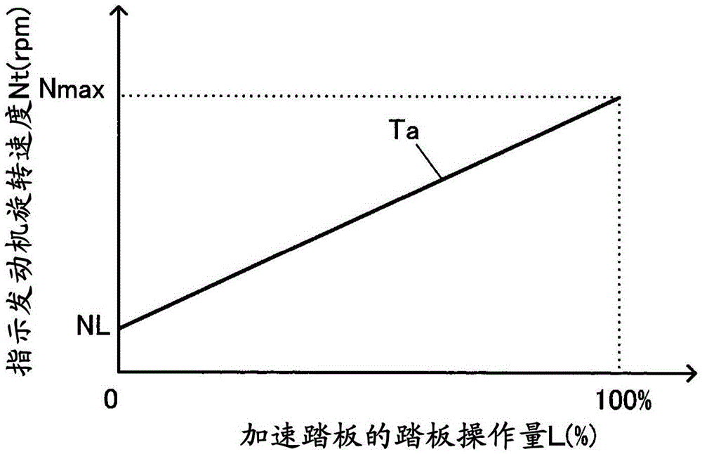
An industrial vehicle provided with an HST travel drive device, wherein the industrial vehicle is further provided with an operation amount detector for detecting the amount of operation of an accelerator pedal, a rotational speed detector for detecting the actual rotational speed of a prime mover, a requested speed calculator for calculating the requested rotational speed of the prime mover on the basis of the amount of operation detected by the operation amount detector, and a prime mover controller for controlling the actual rotational speed on the basis of the requested rotational speed calculated by the requested speed calculator. The requested speed calculator calculates the rate of acceleration of the requested rotational speed on the basis of the difference between the requested rotational speed and the actual rotational speed detected by the rotational speed detector when the requested rotational speed is greater than a prescribed value, and calculates the requested rotational speed on the basis of the calculated rate of acceleration.

Description

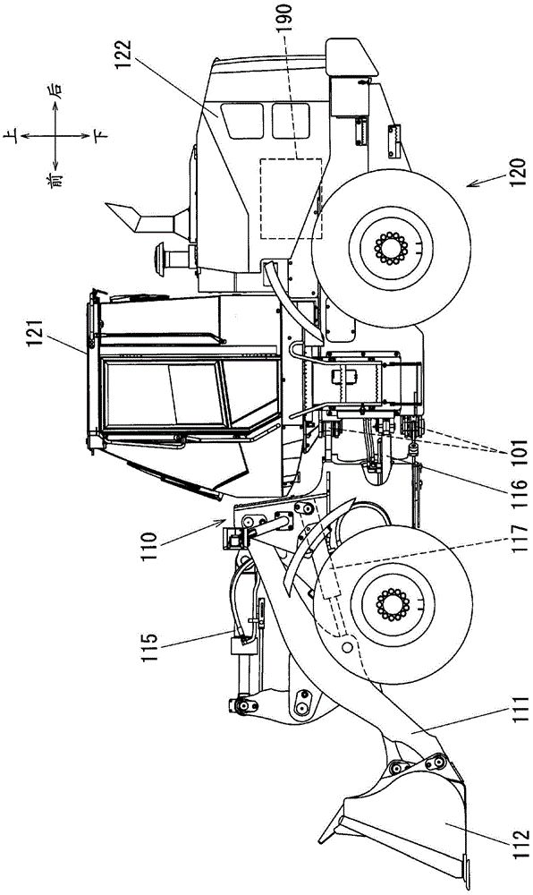
technical field [0001] The present invention relates to a work vehicle equipped with an HST (HydroStatic Transmission) traveling drive device. Background technique [0002] In a work vehicle equipped with an HST travel drive device in which a hydraulic motor is connected to a hydraulic pump in a closed circuit, the hydraulic pump is directly connected to the engine, and the movement of the vehicle is easily affected by changes in the engine rotational speed, so the vehicle as a whole tends to be displaced in the front-rear direction. Shaky swing. [0003] Therefore, in a work vehicle equipped with an HST travel drive device, a technique has been proposed to limit the increase rate per unit time of the actual accelerator operation amount to a preset limit value, thereby reducing the sudden and large acceleration during start-up and acceleration. Excessive acceleration in the case of an acceleration operation (refer to Patent Document 1). [0004] prior art literature [00...

Claims


Application Information

Patent Timeline
Patent Type & Authority Applications(China)
IPC IPC(8): F02D45/00F02D29/02F02D29/04F16H61/40
CPCF02D29/04F02D41/0097F02D41/021F02D41/0215F02D41/12F02D2200/602F16H59/18F16H61/42F16H63/50F02D41/107F02D2200/101F02D2200/1012E02F9/2066
Inventor 青木勇菊池圭吾田中哲二大前贤太郎
Owner HITACHI CONSTRUCTION MACHINERY CO LTD
Features
  • R&D
  • Intellectual Property
  • Life Sciences
  • Materials
  • Tech Scout
  • Unparalleled Data Quality
  • Higher Quality Content
  • 60% Fewer Hallucinations
Learn More