
High and low velocity transmission structure of micro tilling machine

A transmission structure, high and low speed technology, applied in agricultural machinery, agricultural machinery and implements, applications, etc., can solve the problems of single forward and backward speed of the micro-tiller, can not meet the actual needs of production, etc., achieve novel structure, increase The effect of output speed

Inactive Publication Date: 2016-05-04
WEIMA AGRI MACHINERY CO LTD
View PDF0 Cites 0 Cited by
  • Summary
  • Abstract
  • Description
  • Claims
  • Application Information

AI Technical Summary

Problems solved by technology

By shifting the positions of the double spur gears on the main shaft and the reverse gear shaft, fast gear, slow gear and reverse gear can be realized. There are few gears, so the forward and reverse speeds of the tiller are relatively single, especially there is only one reverse gear. There are great limitations in actual farming and cannot meet the actual needs of production

Method used


Image

  • High and low velocity transmission structure of micro tilling machine
  • High and low velocity transmission structure of micro tilling machine

Examples


Embodiment Construction

[0015] The present invention will be further described below in conjunction with the embodiments and accompanying drawings.

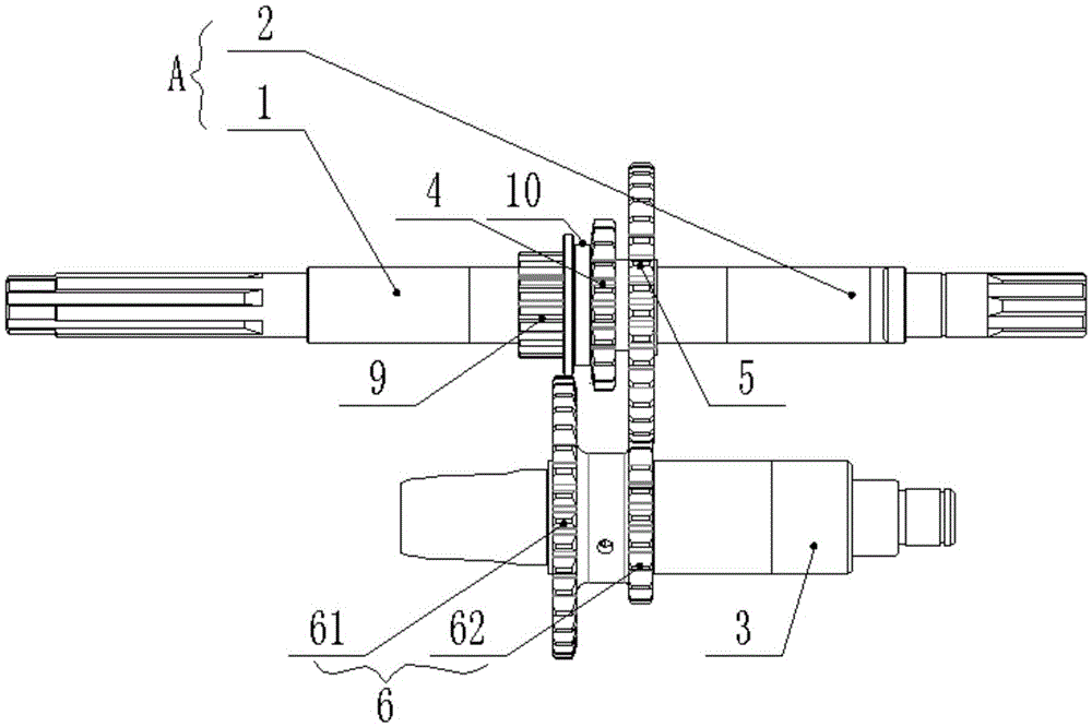
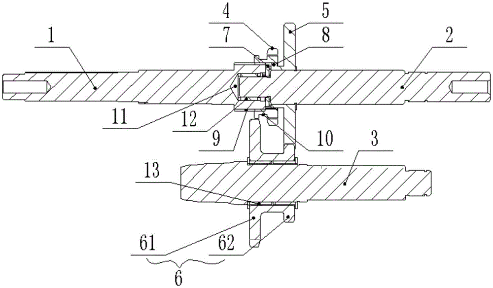
[0016] like Figure 1-2 As shown, a high and low speed transmission structure of a tiller includes a main shaft A and an auxiliary shaft 3 arranged in parallel, wherein the main shaft A includes a first main shaft 1 and a second main shaft 2 arranged on the same straight line, and the first main shaft 1 Either end is connected to any end of the second main shaft 2 with a looper, that is, an inner cavity 11 is provided at the end of the first main shaft 1 close to the second main shaft 2, and the second main shaft 2 is close to the first main shaft 2. One end of the main shaft 1 protrudes into the inner cavity 11, and the protruding end of the second main shaft 2 is connected with the wall of the inner cavity 11 through a first needle bearing 12, and an input gear is set on the first main shaft 1 4. An input gear control slot 10 is provided on the input...


PUM


Abstract

The invention discloses a high and low velocity transmission structure of a micro tilling machine. The high and low velocity transmission structure includes a master shaft and a slave shaft which are parallelly arranged; the master shaft includes a first master shaft and a second master shaft which are on the same straight line; any one end of the first master shaft and any one end of the second master shaft are in movable sleeved connection; an input gear sleeves the first master shaft, and the input gear can axially slide along the first master shaft; a first clutch tooth is arranged on the input gear; one end of the second master shaft, close to the first master shaft, is fixedly sleeved with a first master gear, and a second clutch tooth is arranged on the first master gear; a first slave gear and a second slave gear movably sleeves the slave shaft; the first slave gear is fixedly connected to the second slave gear to form slave shaft double gears; the second slave gear is engaged with the first master gear, when the input gear axially slides along the first master shaft, the input gear is engaged with the first slave gear or the first clutch tooth is engaged with the second clutch tooth. Through the technical scheme, the master shaft can provide the high input velocity and the low input velocity to a gearbox of the micro tilling machine.

Description

technical field [0001] The invention belongs to the technical field of agricultural machinery, and in particular relates to a high-low speed transmission structure of a tiller. Background technique [0002] Tillers are powered by small diesel engines or gasoline engines, and have the characteristics of light weight, small size, and simple structure. Tillers are widely used in dry land, paddy fields, orchards, etc. in plains, mountains, and hills. Equipped with corresponding equipment, it can be used for pumping, power generation, spraying, spraying and other operations, and can also be towed for short-distance transportation. The tiller can be used freely in the field, which is convenient for users to use and store, eliminating the need for large-scale agricultural machinery to enter The troubles of mountainous fields are the best choice for farmers and consumers to replace cattle plowing. [0003] The engine and the gearbox of the traditional tiller are only directly conn...

Claims


Application Information

Patent Timeline
IPC IPC(8): A01B71/06
CPCA01B71/06
Inventor 严华
Owner WEIMA AGRI MACHINERY CO LTD
Learn More