

Remotely controllable pet feeder
A remote control and feeder technology, applied in the field of pet feeders, can solve the problems that pets cannot be properly cared for, there is no free space for activities, food expires, etc.
- Summary
- Abstract
- Description
- Claims
- Application Information
AI Technical Summary
Problems solved by technology
Method used
Image

Examples
no. 1 example
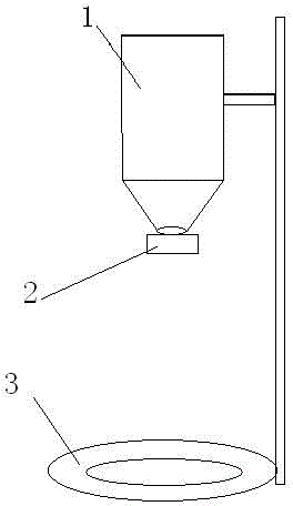
[0023] Such as figure 1 , the first embodiment of the present invention includes a material holding device 1, a material leakage switch 2 and a feeding container 3; The switch 2 is located at the opening of the material holding device, and the material leakage switch 2 is opened or closed under the control of the radio signal.
[0024] Wherein, an opening can also be provided on the top of the material holding device 1, and a common cover is added on it, and such a design is beneficial for the pet owner to put food into the material holding device 1. As a preferred example, the material leakage opening below the material holding device 1 can be set smaller, which is conducive to controlling the speed at which the food material leaks from the material leakage opening into the food-taking container 3 .
[0025] The material holding device 1 can be fixed by a bracket.
[0026] The usage method of the first embodiment is set forth below in order to explain its principle more cle...
no. 2 example
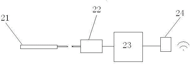
[0029] In this embodiment, on the basis of the first embodiment, the material leakage switch is designed to include a material blocking plate 21, a motor 22, a controller 23 and a wifi module 24; the material blocking plate 21 and the motor 22 have a transmission connection, and the material blocking plate 21 The plate 21 is located at the opening of the material holding device, and is used to close or open the opening of the material holding device driven by the motor 22; the controller 23 has a signal connection with the motor 22, and the WiFi module 24 has a signal connection with the controller 23. Connection; the WiFi module 24 is used to receive a remote control signal through the network, and the controller controls the motor 22 to drive the material baffle under the action of the remote control signal.
[0030] In this embodiment, the controller is connected to the Internet through the WiFi module, and can communicate with the remote controller in the Internet. When th...
no. 3 example
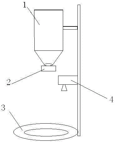
[0034] This embodiment includes a material holding device 1, a material leakage switch 2, a feeding container 3 and an image acquisition device 4; the feeding device 1 is located above the feeding container 3, with the opening facing downward and aligned with the feeding container 3; The material switch 2 is located at the opening of the material holding device, and the material leakage switch 2 is opened or closed under the control of the radio signal. Specifically, the image acquisition device 4 may be a camera.
[0035] The leakage switch in this embodiment can adopt the structure in the second embodiment. The image acquisition device 4 has a signal connection with the controller 23 in the material leakage switch, and the image acquisition device 4 is used to collect the image of the feeding container and transmit it to the controller 23 .
[0036] The usage method of the third embodiment is explained below, so as to explain its principle more clearly.
[0037] Before the...
PUM
 Abstract
Description
Claims
Application Information