Air cylinder driving rail type foam scrubbing rod releasing device

A cylinder-driven, delivery device technology, applied in the direction of mining fluid, wellbore/well components, earthwork drilling and production, etc., can solve the problems of high labor intensity, slow drop of bubble row rods, hidden safety hazards of operators, etc., to improve work efficiency Efficiency, increase delivery speed, and reduce labor intensity

Active Publication Date: 2018-02-09
SOUTHWEST PETROLEUM UNIV
View PDF8 Cites 2 Cited by
  • Summary
  • Abstract
  • Description
  • Claims
  • Application Information

AI Technical Summary

Problems solved by technology

[0003] At present, the implementation of solid foam drainage and gas recovery technology in most gas wells requires on-site operation by staff, and the foam row sticks fall by their own gravity, which is labor-intensive and poses safety hazards to the operators. Irregularity and other shortcomings make it difficult to realize automatic management of liquid-loaded gas wells, which affects the effect of foam drainage and gas recovery technology, increases the cost of drainage and gas recovery operations, and makes it impossible to remove wellbore fluid well and affect the normal production of gas wells, especially For marginal wells with relatively small gas production, the above problems are particularly serious

Method used


Image

  • Air cylinder driving rail type foam scrubbing rod releasing device
  • Air cylinder driving rail type foam scrubbing rod releasing device
  • Air cylinder driving rail type foam scrubbing rod releasing device

Examples


Embodiment Construction

[0021] Below in conjunction with accompanying drawing, the present invention will be further described:

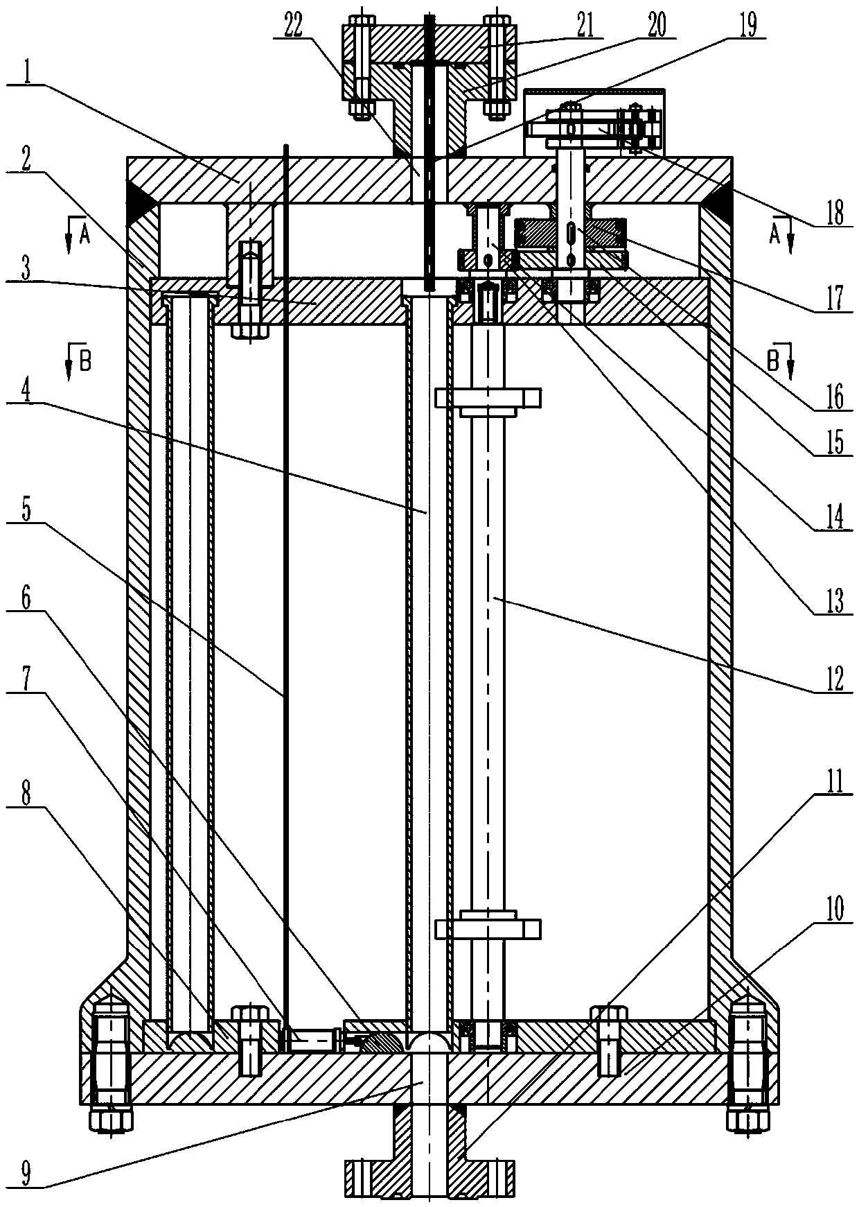
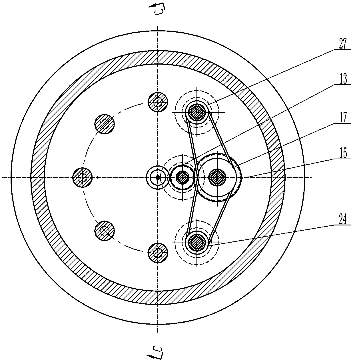
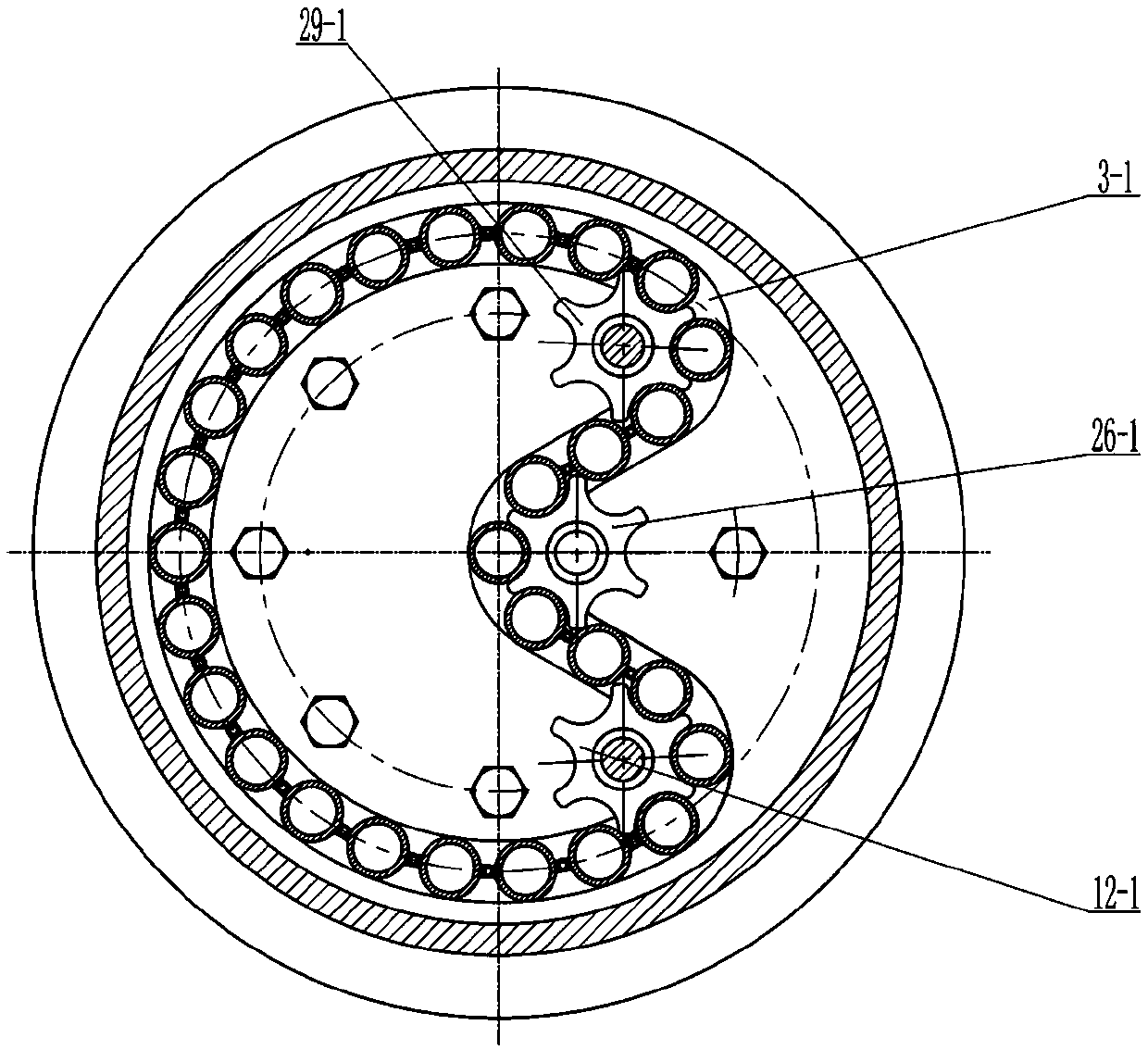
[0022] like figure 1 , figure 2 , Figure 4 , Figure 5 and Figure 6As shown, a cylinder-driven track-type foam row rod feeding device consists of an upper cover plate 1, a housing 2, an upper limit wheel 3, a charging cylinder 4, an air pipe 5, a stopper 6, a stopper cylinder 7, and a lower limiter wheel 8. Lower cover plate 10, wellhead connecting flange 11, drive shaft 12, pinion gear 13, pinion gear shaft 14, large gear 15, large gear shaft 16, large pulley 17, ratchet mechanism 18, air nozzle 19, upper method Lan 20, flange cover 21, indexing cylinder 23, small pulley I24, small pulley shaft I25, driven shaft I26, small pulley II27, small pulley shaft II28 and driven shaft II29 form. The upper cover plate 1 is installed above the shell 2 and connected with the shell 2 by welding. The center of the upper cover plate 1 is provided with a charging hole 22. The low...


PUM


Abstract

The invention relates to an air cylinder driving rail type foam scrubbing rod releasing device applied to the field of drainage and gas recovery of natural gas wells. An upper cover plate is mounted and welded to the top of a shell, a material loading hole is formed in the center of the upper cover plate, a lower cover plate is mounted and connected to the bottom of the shell through bolts, a material releasing hole is formed in the center of the lower cover plate, and an upper limiting wheel and a lower limiting wheel are mounted in the shell. An annular rail is arranged on the upper limitingwheel and the lower limiting wheel, material loading barrels are sequentially arranged in the annular rail, a driving shaft is provided with a pusher claw, and the driving shaft is mounted on the upper limiting wheel and the lower limiting wheel. The pusher claw clamps the material loading barrels, a transportation cylinder drives a ratchet wheel to provide power, the ratchet wheel drives the material loading barrels to move in the rail through the driving shaft, and when the material loading barrels move to the position of the material releasing hole, a foam scrubbing rod falls into a rockshaft through the material releasing hole. Compared with the prior art, the foam scrubbing rod releasing device is arranged to be aligned with a well mouth, the functions of remotely-controlled automatic releasing, one-time installation and repeated releasing of the foam scrubbing rod are achieved, the foam scrubbing rod releasing device is simple in operation, safe and reliable, the labor intensityis relieved, and the working efficiency is improved.

Description

technical field [0001] The invention relates to the field of drainage and gas recovery of natural gas wells, in particular to a cylinder-driven rail-type foam row rod feeding device. Background technique [0002] In the process of natural gas exploitation, due to the gradual decrease of gas reservoir storage pressure and natural gas flow velocity, the formation water or condensate of the gas well cannot be carried out of the wellbore by the natural gas flow, resulting in wellbore fluid accumulation, seriously affecting the normal production of the gas well, and even Water flooding of gas wells, rapid and effective removal of fluid accumulation in the wellbore of gas wells has become one of the main tasks of gas production workers. The foam row rod feeding device is mainly used for the wellhead of gas production. By putting the foam row rod into the gas well, it dissolves and foams with the water in the gas well, and the natural gas is taken out of the gas well to realize the...

Claims


Application Information

Patent Timeline
IPC IPC(8): E21B43/22
CPCE21B43/16
Inventor 蒋发光李大洋张启伟钱燕叶哲伟马海峰朱云鹏朱钵
Owner SOUTHWEST PETROLEUM UNIV
Why Eureka
Try Eureka