Heat accumulating type oxidation device for catalysis denitration

A technology for catalytic denitration and oxidation devices, applied in incinerators, lighting and heating equipment, chemical instruments and methods, etc., can solve the problems of low efficiency and large area, and achieve low manufacturing and operating costs, reasonable structure, Good energy saving effect

Inactive Publication Date: 2016-05-04
HARBIN INST OF TECH AT WEIHAI
View PDF5 Cites 10 Cited by
  • Summary
  • Abstract
  • Description
  • Claims
  • Application Information

AI Technical Summary

Benefits of technology

The technical purpose described by this patented technology is that it allows for effective removal or destruction of harmful gases from exhaust gas streams while minimizing production cost compared to previous methods like absorption into liquid solvents. This makes them more efficient than current technologies such as incinerators.

Problems solved by technology

This patented technical solution described in the patents describes various ways to remove harmful gases from industrial processes or environmental concerns such as emissions caused by volatilization during burning process. These techniques include use of different types of materials like activated carbon carriers, metal carbons, ceramics, porous silica, zeolite, lithium ion batteries, iron based panel products, and cathode ray tubes. However, each technique requires an expensive apparatus installation due to their complexity structure and poor performance compared to traditional technologies. Therefore, finding alternative solutions without requiring excessively long periods of time and expenses would help address issues related to emission control standards.

Method used


Image

  • Heat accumulating type oxidation device for catalysis denitration
  • Heat accumulating type oxidation device for catalysis denitration

Examples


Embodiment 1

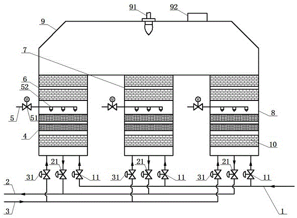
[0014] From figure 1 It can be seen that a regenerative oxidation device for catalytic denitrification includes a first regenerator 6, a second regenerator 7, a third regenerator 8 and an oxidation chamber 9. The oxidation chamber 9 is fixedly installed in the above On the top of the three regenerators, the oxidation chamber 9 is provided with a burner 91 and an explosion-proof door 92, and the explosion-proof door 92 plays a role in releasing pressure during explosion. A regenerator layer 10 is installed inside each regenerator, and below each regenerator is fixedly connected the intake pipe 1, the exhaust pipe 2, the blowback pipe 3, the intake valve 11, the exhaust valve 21, and the blowback Valve 31. Specifically, the intake pipe 1 is divided into three sub-pipes, which are respectively connected to the regenerator 6, the regenerator 7 and the regenerator 8, and the exhaust gas containing VOCs is controlled to enter through the three intake valves 11; the exhaust pipe 2 an...

Embodiment 2

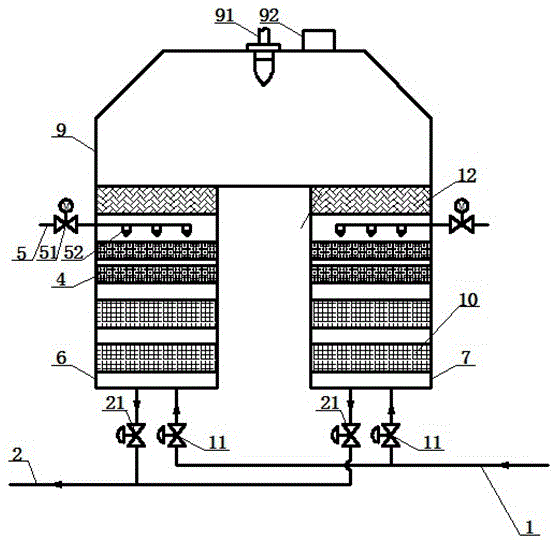
[0026] From figure 2 It can be seen that a regenerative oxidation device for catalytic denitration includes a first regenerator 6, a second regenerator 7 and an oxidation chamber 9. The oxidation chamber 9 is fixedly installed on the top of the two regenerators. , The oxidation chamber 9 is provided with a burner 91 and an explosion-proof door 92, and the explosion-proof door 92 plays a role in releasing pressure during explosion. A regenerator layer 10 is installed inside each regenerator, and an intake pipe 1 and an exhaust pipe 2 are fixedly connected below each regenerator. Specifically: the intake pipe 1 is divided into two sub-pipes, respectively connected to the regenerator 6 and the regenerator 7, and the exhaust gas containing VOCs is controlled to enter through the intake valve 11; the exhaust pipe 2 also passes through the exhaust gas respectively Valve 21 controls the outflow of gas.

[0027] The feature of this embodiment is that each regenerator is also installed...


PUM


Abstract

The invention relates to a heat accumulating type oxidation device for catalysis denitration. The heat accumulating type oxidation device comprises heat accumulation chambers and an oxidation chamber. The oxidation chamber is fixedly installed on the tops of the multiple heat accumulation chambers. A combustor and an explosion door are arranged on the oxidation chamber. A heat accumulating body layer is installed inside each heat accumulation chamber. An air inlet pipeline, an air exhaust pipeline, an air inlet valve and an air exhaust valve are fixedly connected below each heat accumulation chamber. A catalysis reducing agent layer and a reduced product nozzle are further installed inside each heat accumulation chamber. The reduced product nozzles are connected with a liquid reduced product pipeline and installed above the catalysis reducing agent layers and spray reduced products to the catalysis reducing agent layer. A valve is installed on the liquid reduced product pipeline. The heat accumulating type oxidation device is reasonable in structure, low in manufacturing and operation cost, small in occupied area, good in energy-saving effect, capable of efficiently treating VOCs and NOx at the same time, and ideal.

Description


Claims


Application Information

Patent Timeline
Owner HARBIN INST OF TECH AT WEIHAI
Why Eureka
Try Eureka