Single-hole linear jet flow mortar making nozzle

A nozzle and linear technology, which is applied in the field of single-hole linear jet slurry-making nozzles, can solve the problems of affecting filling quality, waste of cementitious materials, and reducing tailings deposition, so as to avoid large-area sand accumulation, facilitate sand accumulation, and improve The effect of filling quality

Inactive Publication Date: 2016-05-04
邓代强 +2
View PDF6 Cites 3 Cited by
  • Summary
  • Abstract
  • Description
  • Claims
  • Application Information

AI Technical Summary

Problems solved by technology

In general, in order to ensure the slurry-making effect of the tailings mortar, the tailings mortar is usually agitated pneumatically with the nozzle of the point jet flow, and the sand release operation is carried out after the mixing is uniform. Occasionally, the concentration of the slurry may be uneven. With the increase of the spray distance, the point jet flow basically changes from a point to a conical shape, and the contact surface with the object is basically a circle, so there is a certain force reduction effect, and the effect is It will be affected, and the impact force of the circular jet surface is difficult to stir up the tightly agglomerated massive tailings, which will affect the stability of the filling concentration. At the same time, this method is time-consuming when emptying the container, and sometimes it will cause tailings Residue, cleaning is not clean, so the concentration fluctuation range of the tailing mortar will be increased, which will seriously affect the filling quality, greatly increase the safety hazards of underground mining, cause the waste of cementitious materials, and increase the cost of filling operations. At this time, a Effective equipment for processing to achieve ideal slurry making and cleaning effects, that is, uniform and rapid mixing of tailings mortar to reduce tailings deposition

Method used


Image

  • Single-hole linear jet flow mortar making nozzle
  • Single-hole linear jet flow mortar making nozzle
  • Single-hole linear jet flow mortar making nozzle

Examples


Embodiment Construction

[0018] The present invention will be further described below in conjunction with drawings and embodiments.

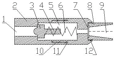
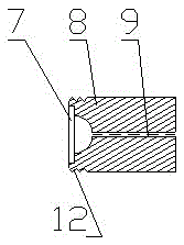
[0019] Referring to the accompanying drawings, this embodiment includes a housing 2, a one-way valve 3, a spring 6 and a nozzle 8, the housing 2 is provided with an air inlet 1 and an air chamber 5; the one-way valve 3 and the spring 6 are installed In the air chamber 5, one end of the spring 6 is connected to the housing 2, and the other end is connected to the one-way valve 3. The one-way valve 3 is provided with a tail rod 4, and the tail rod 4 is located in the spring 6. When the high-pressure air passes through the air inlet 1, it opens the check valve 3 and enters the air chamber 5. The opening and closing state of the check valve 3 is controlled by the spring 6. If there is no high-pressure air supply, the check valve 3 is controlled by the spring 6. Push to the closed state; the nozzle 8 is installed on the housing 2 and communicates with the air chamber 5; the ...


PUM


Abstract

A single-hole linear jet flow mortar making nozzle comprises a shell, a one-way valve, a spring and a nozzle body. The shell is internally provided with an air inlet hole and an air chamber, the one-way valve and the spring are installed in the air chamber, one end of the spring is connected with the shell, and the other end of the spring is connected with the one-way valve; a tail rod is arranged on the one-way valve, and the tail rod is located in the spring; when high-pressure air passes through the air inlet hole, the high-pressure air pushes open the one-way valve and then enters the air chamber, switching-on and switching-off states of the one-way valve are controlled by the spring, and if the high-pressure air is not supplied, the one-way valve is pushed by the spring to the switching-off state; the nozzle body is installed on the shell and communicated with the air chamber, an incision rubber pad is arranged in the nozzle body, and a nozzle hole of the nozzle body is of a platode structure. By means of the single-hole linear jet flow mortar making nozzle, uniform tail mortar can be prepared rapidly and efficiently, the cleaning effect is significant, processing is convenient, the structure is simple, and the making cost is low.

Description

technical field [0001] The invention relates to a nozzle, in particular to a single-hole linear jet slurry-making nozzle. Background technique [0002] In the process of making tailing mortar, in order to stir the filling tailing mortar evenly and avoid excessive sand accumulation in the container, it is necessary to use some devices to achieve better mixing and sand cleaning effects. Therefore, appropriate technical measures must be taken, that is, different devices must be used to stir the tailing mortar. When different devices are used, the uniformity and effect of slurry making will be different. In general, in order to ensure the slurry-making effect of the tailings mortar, the tailings mortar is usually agitated pneumatically with the nozzle of the point jet flow, and the sand release operation is carried out after the mixing is uniform. Occasionally, the concentration of the slurry may be uneven. With the increase of the spray distance, the point jet flow basically c...

Claims


Application Information

Patent Timeline
Patent Type & Authority Applications(China)
IPC IPC(8): B05B1/30B05B1/04
CPCB05B1/04B05B1/3006
Inventor 邓代强邓代君易波
Owner 邓代强
Why Eureka
Try Eureka