Method and system for producing liquefied natural gas (LNG)

a technology of natural gas and liquefied gas, applied in the direction of refrigeration and liquidation, lighting and heating apparatus, solidification, etc., can solve the problems of unsuitable lng-based arrangements, unsatisfactory applications, and undesirable products, so as to improve the energy efficiency of the process, improve the efficiency of the gas expansion process, and optimise the application

Active Publication Date: 2015-10-06
ARAGON AS
View PDF20 Cites 1 Cited by
  • Summary
  • Abstract
  • Description
  • Claims
  • Application Information

AI Technical Summary

Benefits of technology

[0019]According to one aspect of the invention is provided a method comprising a fractionation column for feeding in of a feed gas, a heat exchanger system for cooling down and partially condensing the overhead gas stream of the fractionation column, a separator to separate the two-phase stream from the heat exchanger system and an appliance for return of fluid from the separator to the fractionation column and feeding this fluid to the upper part of the column as reflux, and an appliance to feed the gas from the separator back to the heat exchanger system for further cooling down and liquefaction to LNG. The invention comprises a closed gas expansion process to liquefy the natural gas, wherein the gas is first fed through a fractionation column where the gas is cooled and separated into an overhead fraction with reduced content of hexane (C6) and heavier components, and a bottom fraction enriched with the heavier hydrocarbons (C6+), furthermore, in that the fractionation column reflux is generated as an integrated part of the system for liquefaction in that the overhead gas is partially condensed. By carrying out the liquefaction in accordance with the invention, production of liquid gas with maximum content of ethane, propane and butane (C2-C4) is achieved at the same time as the efficiency of the gas expansion process is increased and the by-production of unstable / volatile fluid with a high content of methane, ethane, LPG (propane+butane) is minimised.
[0021]The aim of the invention is to render liquefaction of gas energy efficient at the same time as the process is kept simple so that the equipment can be used offshore. In particular the invention is useful on floating installations since the by-production of condensate during the liquefaction is minimised and the efficiency is maximised (the need for fuel gas is minimised).
[0025]The present invention represents a considerable optimisation for application offshore, and especially on a floating unit, in that a relatively simple and robust gas expansion process is used for liquefaction of natural gas, and in that the energy efficiency of this process is increased at the same time as the amount of liquid gas is maximised by maximising the content of ethane and LPG, at the same time as the amount of hydrocarbons heavier than methane which is separated out as bi-products in the liquefaction process is minimised.

Problems solved by technology

Because of the complexity of large, “Base load” systems, the arrangements used therein are not suitable for many applications, for example offshore applications.
In addition, it is undesirable to handle products other than the LNG, as hydrocarbons lighter than C5 can, on the whole, not be stored or transported safely without being cooled down or under pressure.
The gas expansion cycle is relatively simple, but is less efficient than the mixed refrigerant cycle.

Method used


Image

  • Method and system for producing liquefied natural gas (LNG)
  • Method and system for producing liquefied natural gas (LNG)
  • Method and system for producing liquefied natural gas (LNG)

Examples


example 1

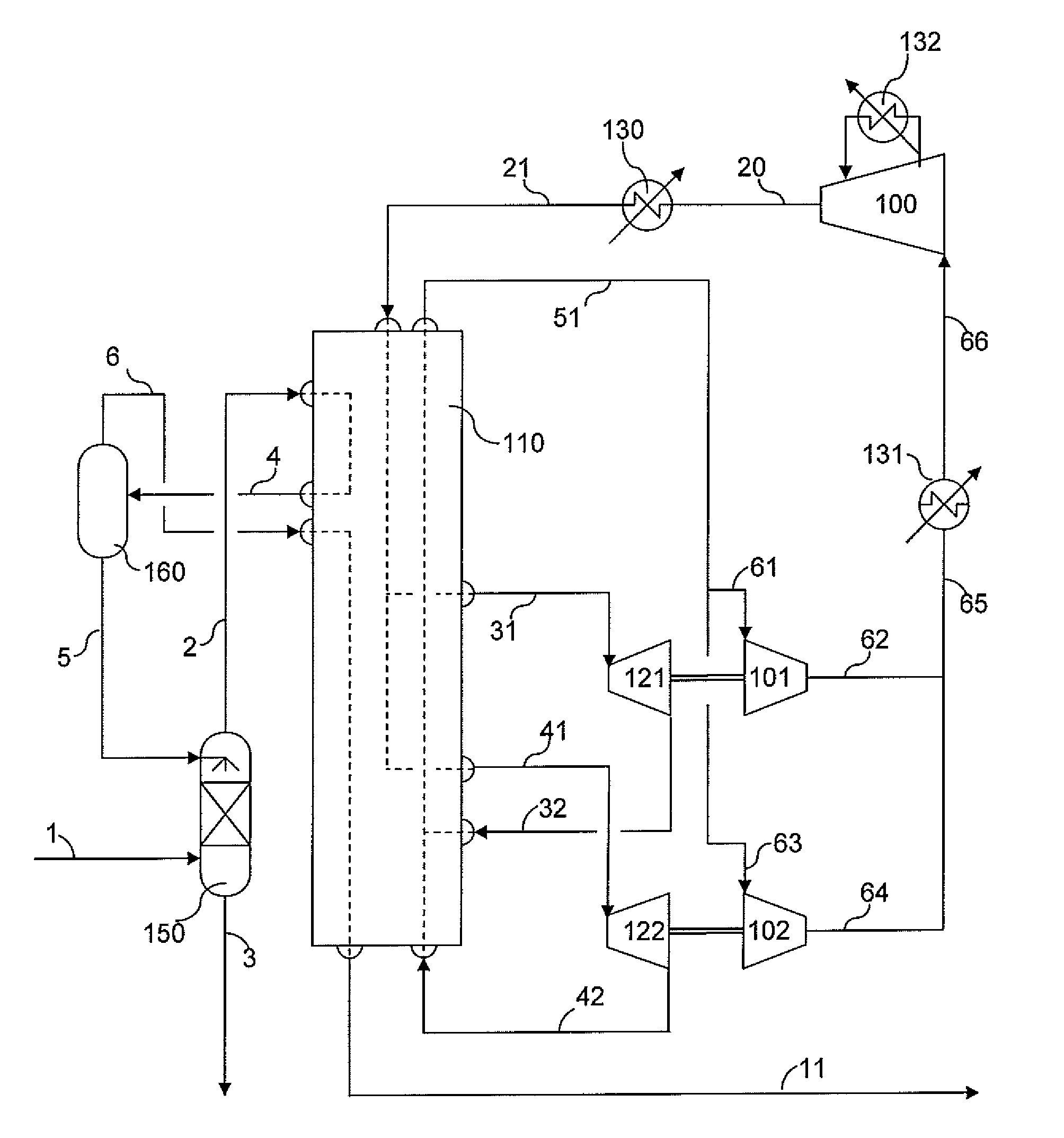
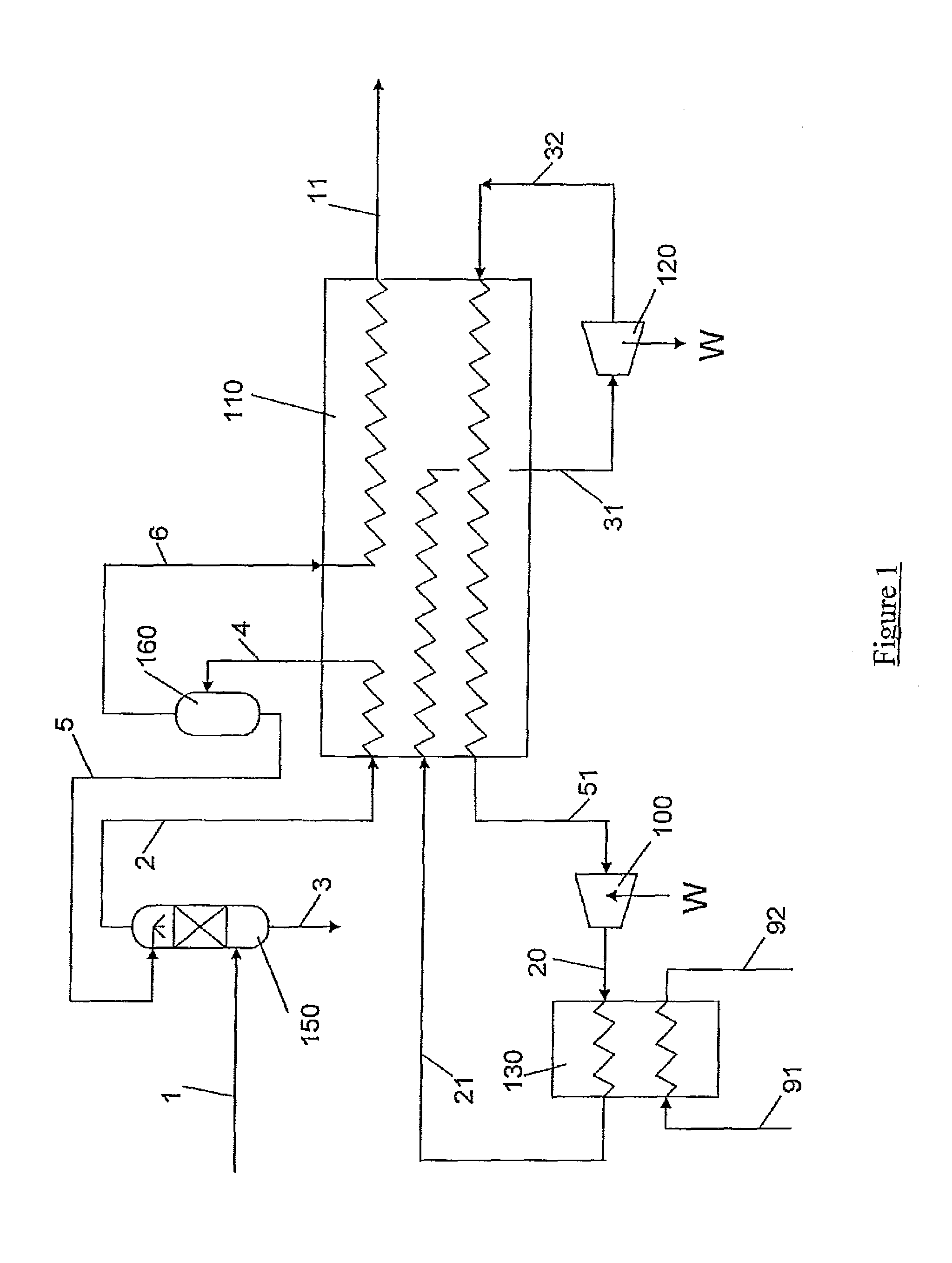
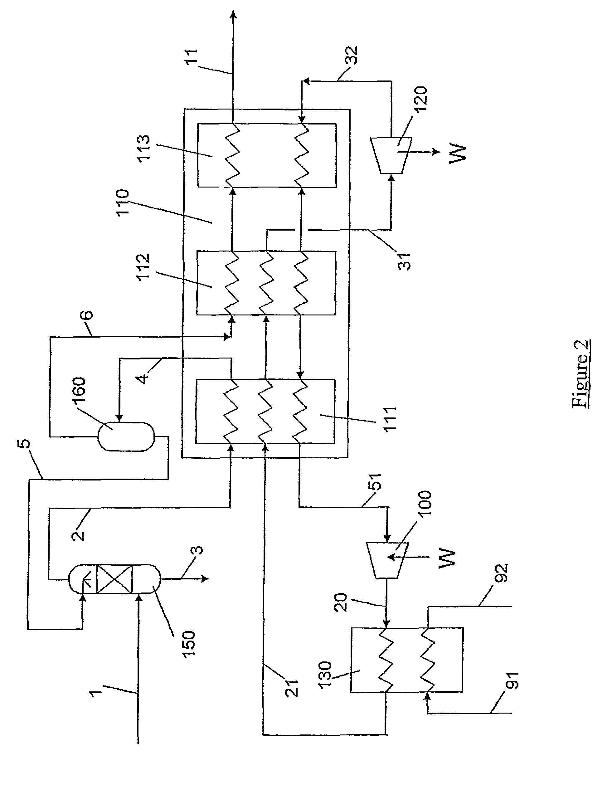
[0072]The example below shows natural gas with 90.4% methane by volume which is to be liquefied, where the invention is used to maximise the amount of liquid gas and at the same time minimise the by-production of unstable hydrocarbon liquid with a high content of ethane, propane and butane. The stream data refer to FIG. 1, 2, 3, 4 or 5.

[0073]

Stream No.12345611Gas fraction    1.00    1.00    0.00    0.95    0.00    1.00    0.00Temperature   40.0   19.2   35.9  −20.0  −20.0  −20.0  −155.0(° C.)Pressure2740273827452725273027232655(kPa abs)Mole flow42324422 444422 23541854185(kmol / h)Mass flow78980 87539 341087539 11969 75541 75541 (kg / h)Molefraction (%)Nitrogen0.51%0.49%0.02%0.49% 0.03%0.52%0.52%Methane90.4%87.4%11.8%87.4% 19.5%91.3%91.3%Ethane4.38%4.53%2.58%4.53% 6.84%4.40%4.40%Propane2.29%2.95%4.17%2.95%15.04%2.27%2.27%i-Butane0.68%1.25%2.80%1.25%11.92%0.65%0.65%n-Butane0.66%1.52%3.79%1.52%17.30%0.62%0.62%i-Pentane0.17%0.70%2.52%0.70%10.57%0.14%0.14%n-Pentane0.17%0.79%3.61%0.79%12.49%...

example 2-5

[0074]The examples below shows example of the percentage of feed gas pr. component in some of the key streams with the present invention, for different methane content in feed gas.

[0075]

PERCENT OF FEED GAS FOR EACH STREAM FORA 97 VOL % METHANE FEED GASCOLUMNCOMPONENTREFLUXLNGCONDENSATEOVERHEADN24.4%100.0%0.0%104.4%C110.7%99.9%0.1%110.6%C249.1%99.4%0.6%148.5%C3146.3%98.2%1.8%244.5%C4363.7%94.7%5.3%458.3%C5701.3%68.0%31.9%769.3%C611.1%0.3%99.7%11.4%C70.1%0.0%100.0%0.1%C80.0%0.0%100.0%0.0%C90.0%0.0%100.0%0.0% C10+0.0%0.0%100.0%0.0%

[0076]

PERCENT OF FEED GAS FOR EACH STREAM FORA 95 VOL % METHANE FEED GASCOLUMNCOMPONENTREFLUXLNGCONDENSATEOVERHEADN23.1%100.0%0.0%103.1%C18.6%99.9%0.1%108.5%C245.7%99.4%0.6%145.2%C3151.6%98.1%1.9%249.7%C4393.5%91.2%8.8%484.6%C5129.8%11.1%88.9%140.9%C60.8%0.0%100.0%0.9%C70.0%0.0%100.0%0.0%C80.0%0.0%100.0%0.0%C90.0%0.0%0.0%0.0% C10+0.0%0.0%0.0%0.0%

[0077]

PERCENT OF FEED GAS FOR EACH STREAM FORA 93 VOL % METHANE FEED GASCOLUMNCOMPONENTREFLUXLNGCONDENSATEOVERHEADN...


PUM


Abstract

A method and system for optimizing the efficiency of an LNG liquification system of the gas expansion type, wherein an incoming feed gas is first separated in a fractionation column by counter current contact with a cold reflux fluid, and a gaseous stream introduced into the heat exchanger system at a reduced temperature such that an intermediate pinch point is created in the warm composite curve.

Description

[0001]This application claims the benefit under 35 USC §119(e) of U.S. provisional application 61 / 138,793 filed 19 Dec. 2008.FIELD OF THE INVENTION[0002]The present invention relates to a method for optimal production of LNG.BACKGROUND[0003]As used herein, the term LNG shall refer to Liquefied Natural Gas, that is Natural gas that has been cooled down such that it condenses and becomes liquid.[0004]As used herein, the term Natural Gas shall refer to a gaseous mixture of hydrocarbons where an essential part is methane.[0005]As used herein, the term LPG shall refer to Liquid Petroleum Gas, that is a gaseous mixture of hydrocarbons comprising propane and butanes.[0006]As used herein, the term “mixed refrigerant cycle” shall refer to a liquification process, known in the art, employing an optimized mixture of a plurality of refrigerants.[0007]As used herein, the term “gas expansion process” or “gas expansion cycle” shall refer to a liquefaction process, known in the art, employing a gas...

Claims


Application Information

Patent Timeline
Patent Type & Authority Patents(United States)
IPC IPC(8): F25J1/00F25J3/00F25J1/02
CPCF25J1/0022F25J1/005F25J1/0037F25J1/0052F25J1/0057F25J1/0072F25J1/0082F25J1/0092F25J1/0097F25J1/0201F25J1/0202F25J1/0204F25J1/0205F25J1/0212F25J1/0215F25J1/0216F25J1/0232F25J1/0238F25J1/0241F25J1/0278F25J1/0281F25J1/0288F25J1/0294F25J2210/06F25J2210/62F25J2215/66F25J2220/64F25J2270/16F25J2270/90
Inventor NILSEN, INGE SVERRE LUND
Owner ARAGON AS
Why Eureka
Try Eureka