Battery cap welding machine

A welding machine and battery cover technology, applied in welding equipment, non-electric welding equipment, laser welding equipment, etc., can solve the problems of welding reliability, low welding precision, low efficiency, and cumbersome operation

Inactive Publication Date: 2016-05-04
JIANGSU SUNPOWER
View PDF6 Cites 1 Cited by
  • Summary
  • Abstract
  • Description
  • Claims
  • Application Information

AI Technical Summary

Problems solved by technology

[0002] In battery production, caps need to be packaged after filling the electrolyte. Traditionally, the caps are manually placed on the battery by manual welding. The operation is cumbersome, the efficiency is low, the welding reliability and welding accuracy are low, and the performance of the battery is affected.

Method used


Image

  • Battery cap welding machine
  • Battery cap welding machine
  • Battery cap welding machine

Examples


Embodiment Construction

[0016] Further description will be made below in conjunction with drawings and embodiments.

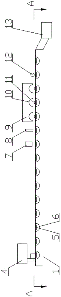
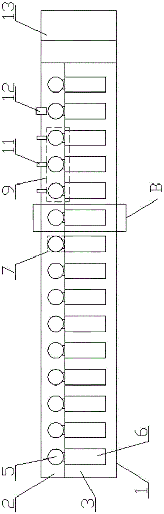
[0017] Figure 1-2 As shown, a battery cap welding machine includes a welding track 1, a cap placement track 2, a battery placement track 3, a cap vibrating screen 4, a welding head 7, a cap turning head 8, a cap closing head 9, and a battery bonding groove 10. Cap pressing cylinder 11, push unloading head 12 and waste collection tank 13 The welding track 1 is driven by a motor to rotate circularly. The welding track 1 is provided with a cap placement track 2 and a battery placement track 3. The battery placement track is set on the cap placement track On one side, a plurality of cap placement holes 5 are sequentially arranged at intervals on the cap placement track 2, the cap vibrating screen 4 corresponds to the cap placement 14 connected to the cap placement hole 5 at one end of the cap placement track 2, and the battery placement track 3 is provided with a plurality of correspondi...


PUM


Abstract

The invention relates to a battery cap welding machine which comprises a cap vibration screen, a welding track, a welding head, a cap overturning pressing head, a cap covering pressing head and a pushing discharge head. The welding track is driven by a motor to circularly rotate and provided with a cap placement track and a battery placement track. The battery placement track is arranged on one side of the cap placement track. The cap placement track is sequentially provided with a plurality of cap placement holes at intervals. The cap vibration screen correspondingly conveys caps and is connected with the cap placement holes in one end of the cap placement track. The battery placement rail is provided with a plurality of battery placement grooves corresponding to the cap placement holes. The welding head, the cap overturning pressing head and the cap covering pressing head are sequentially arranged above the cap placement holes in the other end of the cap placement track in the conveying direction of the track, and the other side of the cap placement track is provided with the pushing discharge head corresponding to the battery placement groove below or behind the cap covering pressing head.

Description

technical field [0001] The invention relates to a battery production equipment, in particular to a battery cap welding machine. Background technique [0002] In the production of batteries, caps need to be packaged after filling the electrolyte. Traditionally, the caps are manually placed on the battery by manual welding. The operation is cumbersome, the efficiency is low, the welding reliability and welding accuracy are low, and the performance of the battery is affected. Contents of the invention [0003] Aiming at the above-mentioned shortcomings of the prior art, the present invention provides a battery cap welding machine with simple structure, convenient operation, fast, safe and stable welding and loading of the cap and the battery, and ensuring the packaging quality. [0004] The technical solution of the present invention is: a battery cap welding machine, which is characterized in that it includes a cap vibrating screen, a welding track, a welding head, a cap tur...

Claims


Application Information

Patent Timeline
Patent Type & Authority Applications(China)
IPC IPC(8): B23K20/10B23K20/26B23K26/21B23K26/70
CPCB23K20/10B23K20/26B23K26/20
Inventor 宋泽斌杨春松赖宇
Owner JIANGSU SUNPOWER
Why Eureka
Try Eureka