
Antagonistic pneumatic muscle-driven bionic knee joint with variable rotation axis and large rotation angle

A technology of pneumatic muscles and large turning angles, applied in the field of bionic robots, can solve problems such as complex mechanism design and difficult control, and achieve the effects of simple mechanism, increased swing angle range, and high ground clearance

Inactive Publication Date: 2017-09-29
CHINA JILIANG UNIV
View PDF1 Cites 0 Cited by
  • Summary
  • Abstract
  • Description
  • Claims
  • Application Information

AI Technical Summary

Problems solved by technology

This design has very good bionic characteristics, but the mechanism design is more complicated, and the curved edge turntable and the elastic part are sliding friction during work, which makes the control more difficult

Method used


Image

  • Antagonistic pneumatic muscle-driven bionic knee joint with variable rotation axis and large rotation angle
  • Antagonistic pneumatic muscle-driven bionic knee joint with variable rotation axis and large rotation angle
  • Antagonistic pneumatic muscle-driven bionic knee joint with variable rotation axis and large rotation angle

Examples


Embodiment Construction

[0012] The present invention will be further described below in conjunction with the accompanying drawings and specific embodiments.

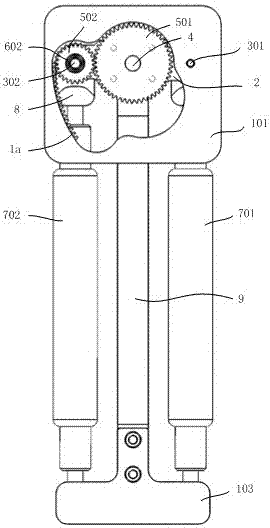
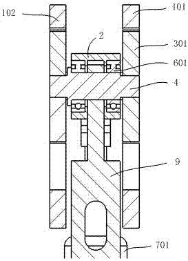
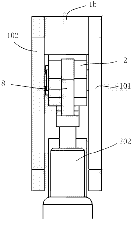
[0013] Such as figure 1 , figure 2 and image 3 As shown, the present invention includes a first upper fixed seat 101, a second upper fixed seat 102, a lower fixed seat 103, an arc-shaped rack 1a, a limit block 1b, a joint seat 2, a first shaft pin 301, a second shaft Pin 302 , joint shaft 4 , first spur gear 501 , second spur gear 502 , first bearing 601 , second bearing 602 , first pneumatic muscle 701 , second pneumatic muscle 702 , I-shaped joint 8 and joint bracket 9 . A joint seat 2 is arranged between the first upper fixed seat 101 and the second upper fixed seat 102, and one end of the joint seat 2 is hinged with the first upper fixed seat 101 and the second upper fixed seat 102 through the first pivot pin 301, and the second upper fixed seat 102 is hinged. One end of a pneumatic muscle 701 is fixedly connected with an I-shaped join...


PUM


Abstract

The invention belongs to the technical field of bionic robots, particularly relates to an antagonism type pneumatic muscle driven variable-speed spindle large-turning-angle bionic knee joint. The knee joint comprises a first upper fixing seat, a second upper fixing seat, a lower fixing seat, an arc-shaped gear rack, a position limiting block, a joint seat, a first shaft pin, a second shaft pin, a joint shaft, a first straight gear, a second straight gear, a first bearing, a second bearing, a first pneumatic muscle, a second pneumatic muscle, an I-type connector and a joint support. The knee joint disclosed by the invention is driven by the pneumatic muscles, and has the advantages of being simple in structure, energy-saving and good in flexibility. According to the bionic knee joint, swing of the joint support realized by pulling of pneumatic muscles is superposed with that of the joint seat realized by gear transmission, so that the pivot angle range of the joint is expanded. Meanwhile, the knee joint well simulates the characteristic that the knee joint of a human can only swing at the single side, so that the knee joint is worthy of application.

Description

technical field [0001] The invention belongs to the technical field of bionic robots, in particular to an antagonistic pneumatic muscle-driven bionic knee joint with variable rotation axis and large rotation angle. Background technique [0002] Traditional rotary joints generally adopt the design of fixed-axis rotation, and the bionic characteristics are not outstanding enough. The rotation of the joints of humans and animals is different from this fixed-axis rotation method, but under the pulling of muscles and tendons, the relative sliding of the two cartilage end surfaces between the joints is promoted. Because the curvature of the end surface of the cartilage is relatively complex, the rotation of the joints of humans and animals can be regarded as a rotation mode in which the position of the shaft changes, that is, the rotation of the variable shaft. The existing joint driving mode is generally driven by a motor, which makes the mechanism complicated and bloated due to...

Claims


Application Information

Patent Timeline
Patent Type & Authority Patents(China)
IPC IPC(8): B25J17/02
CPCB25J17/0258
Inventor 王斌锐沈国阳张斌王飞洋干苏金英连
Owner CHINA JILIANG UNIV
Learn More