Water-borne electronic remote control releaser

An electronic remote control and releaser technology, applied in ships, cargo handling equipment, passenger handling equipment, etc., can solve the signal transmission and reception that easily affects the wireless control system, cannot meet the needs of marine survey instruments or equipment, and has no solution to be released. It can solve problems such as object shaking or rotation, and achieve the effect of promoting the application value, releasing the action and time accurately, and ensuring the requirements of safe operation.

Active Publication Date: 2016-05-04
THE FIRST INST OF OCEANOGRAPHY SOA
View PDF7 Cites 6 Cited by
  • Summary
  • Abstract
  • Description
  • Claims
  • Application Information

AI Technical Summary

Problems solved by technology

Because of the electromagnetic structure, it is easy to affect the signal transmission and reception of the wireless control system, resulting in malfunction, and there is also a certain degree of wear between the release sleeve, the movable sleeve and the release pin, and there is a danger of misoperation; and its design The purpose is to release objects to be released to simulate high-altitude workers. The release weight is generally within 200kg, and the gravity it bears is relatively small. It also cannot meet the needs of marine survey instruments or equipment; in addition, it does not solve the problem of shaking or rotating objects to be released. question

Method used


Image

  • Water-borne electronic remote control releaser
  • Water-borne electronic remote control releaser
  • Water-borne electronic remote control releaser

Examples


Embodiment approach 1

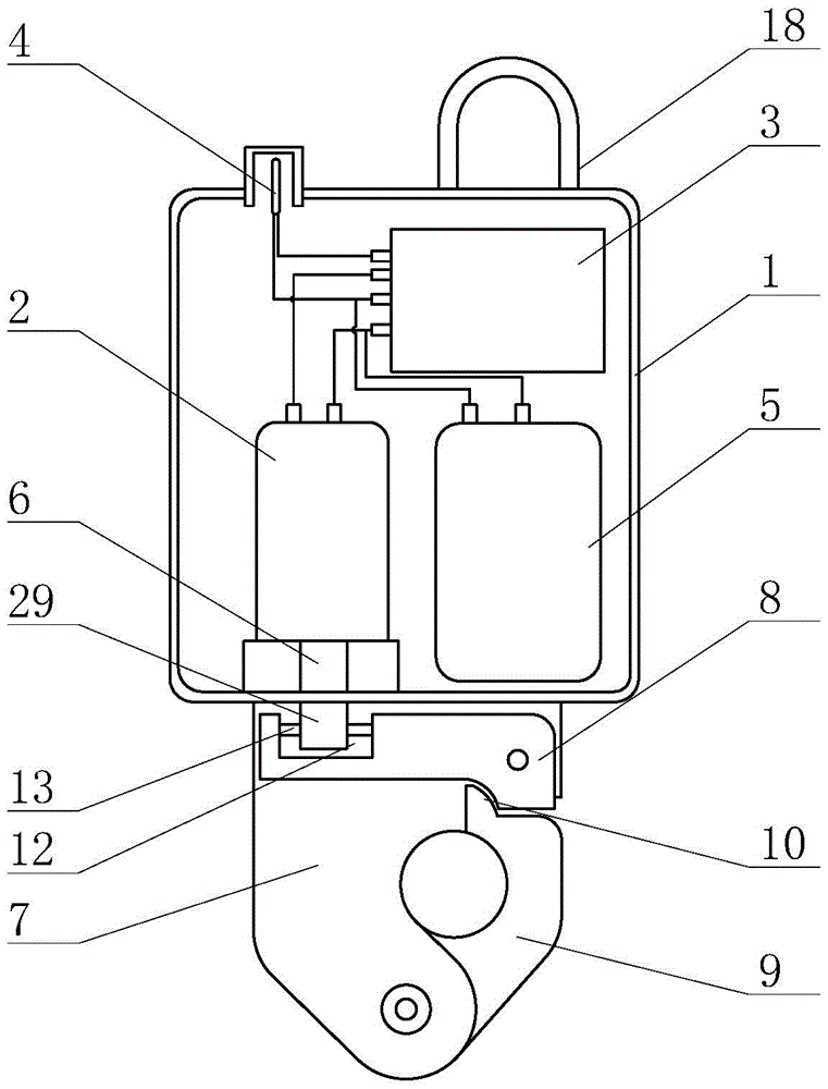
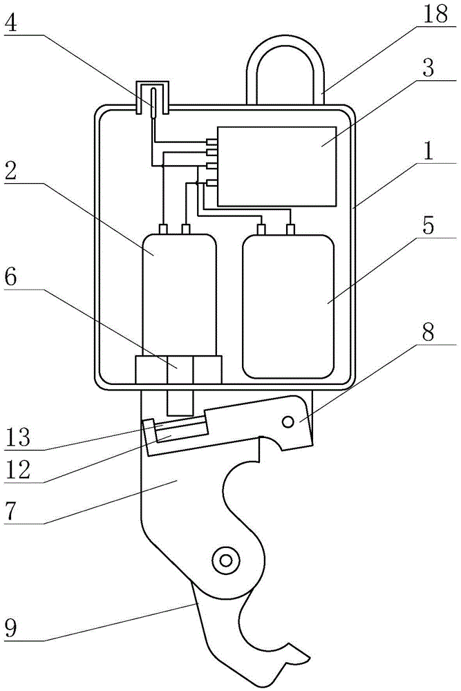
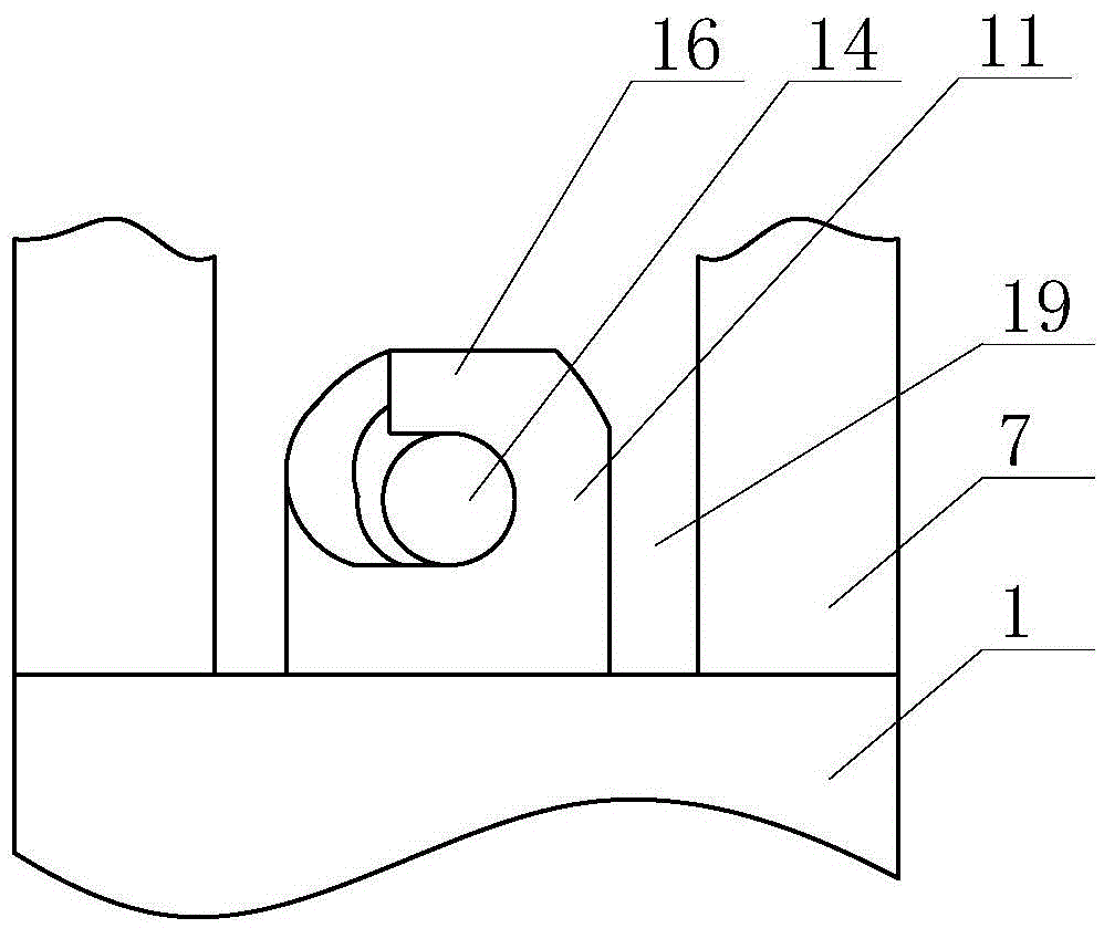
[0041] Such as Figure 1-6 As shown, the release action mechanism 29 in this embodiment includes a fixer 11 arranged at the lower end of the motor shaft 6, a groove 12 is set at the end of the movable block 8, and the fixer 11 extends into the groove 12; A horizontal connecting rod 13 is arranged in the groove 12, and the two ends of the connecting rod 13 are fixed with the movable block; The arc-shaped through groove 17 is opposite to and forms a channel 14 for accommodating the connecting rod. When the motor shaft 6 moves, the connecting rod 13 can be dropped from the locking tooth 17 or the connecting rod 13 and the locking tooth 17 can be fixed.

[0042] Release action mechanism 29 also can adopt following structure in addition: comprise the external thread that is arranged on motor shaft 6 lower ends, the end of movable block 8 is provided with the screw hole that cooperates with external thread, can promote movable block 8 ends when motor shaft 6 moves Move down around ...

Embodiment approach 2

[0046] Such as Figure 7-10 As shown, the difference between this embodiment and the first embodiment is that a rotating mechanism 30 is added between the suspension ring 18 and the first housing 1, and the upper and lower connection and installation are realized through the rotating mechanism 30. The rotating mechanism 30 includes a horizontal plate 20 1. The second housing 23 formed by the shell 21 and the ring end cover 22, the lower end of the suspension ring 18 is fixed to the horizontal plate 20; the vertical connecting shaft 24 is installed through the bearing in the second housing 23, and the connecting shaft 24 The lower end protrudes from the ring end cover 22 and is fixed with the first housing 1. The middle part of the connecting shaft 24 is provided with a radial arc groove 25, and an elastic member 26 is installed in the arc groove 25. The inner end of the elastic member 26 It is fixed with the connecting shaft 24, and a brake block 27 is installed on its outer e...


PUM


Abstract

A water-borne electronic remote control releaser comprises a first shell, a remote control unit and a release hook assembly. A direct-current motor and a controller are installed in the first shell. A motor shaft of the first-current motor stretches out of the first shell downwards. The release hook assembly comprises a side plate, a hook body and a movable block. The upper portion of the side plate and the first shell are fixed, one side of the upper portion of the side plate is hinged to the movable block, and the lower portion of the side plate is hinged to one end of the hook body. A clamping structure matched with the free end of the hook body is arranged at the end, close to the hinge point of the movable block and the side plate, of the movable block, and a release movement mechanism is arranged between the other end of the movable block and the motor shaft, and can control the movable block to be separated from the free end of the hook body. Automatic placing of an instrument or equipment is achieved in a remote control manner, and placing is stable and accurate. The movable block and the hook body are provided with a lever movement structure, so that the weight of a to-be-released object capable of being borne by the releaser is increased. By means of an arranged rotating mechanism, when the to-be-released object shakes or rotates, movement transfer can be stopped to guarantee the placing effect, quality and safety.

Description

technical field [0001] The invention relates to an automatic release device, which belongs to the technical field of marine survey, in particular to a marine electronic remote control release device for remote and safe release of instruments or equipment waiting to be released on a marine survey ship. Background technique [0002] In the process of marine survey and observation, various instruments or equipment are used. Because the heavy instruments or equipment such as gravity anchors are usually more than 2 tons, some even weigh 3 tons, they need to be released according to the location and environmental requirements. Generally, a winch is used to hoist the instrument or equipment out of the ship's side, and the fixed-point delivery is controlled by a mechanical or electric releaser. [0003] The existing mechanical release device includes a release hook and a mechanical locking device. During the release process, a manual pull wire is used to connect the mechanical locki...

Claims


Application Information

Patent Timeline
Patent Type & Authority Applications(China)
IPC IPC(8): B63B27/00
CPCB63B27/00
Inventor 王冠琳李淑江范斌高秀敏
Owner THE FIRST INST OF OCEANOGRAPHY SOA
Why Eureka
Try Eureka