Oar angle and height positioning device

A positioning device and angle technology, which is applied in transportation and packaging, ship propulsion, ship parts, etc., can solve problems such as not well solved, rough production, inaccurate, etc., and achieve convenient and improved positioning devices for the angle and height of the oars efficiency effect

Active Publication Date: 2016-05-04
马菁
View PDF8 Cites 0 Cited by
  • Summary
  • Abstract
  • Description
  • Claims
  • Application Information

AI Technical Summary

Problems solved by technology

[0003] In the past, each crew member could only use different materials to make paddle angle positioning devices in their own way, such as cocktail straws, metal wires, wooden sticks, etc. This type of device is crudely made, which is neither convenient nor easy to use. imprecise
Even CN201510123094.6 and CN201520158881.X of the prior art have proposed a device for measuring height, but they have not solved well how to combine the angle and height of the oars when the athlete is rowing together for positioning control, so as to realize Rowing Faster, Power Transfer Efficiently Better

Method used


Image

  • Oar angle and height positioning device
  • Oar angle and height positioning device
  • Oar angle and height positioning device

Examples


Embodiment Construction

[0032] The present invention will be described in detail below in conjunction with the accompanying drawings.

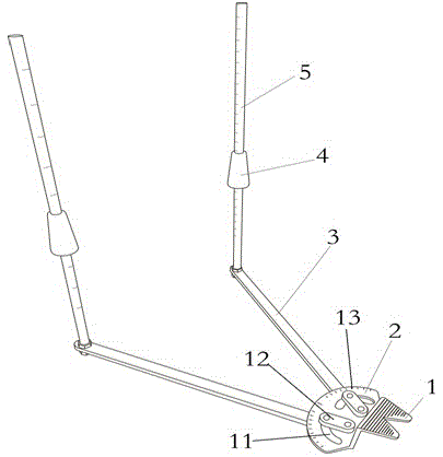
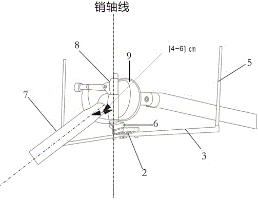
[0033] refer to Figure 1 to Figure 3 , a paddle angle and height positioning device, comprising:
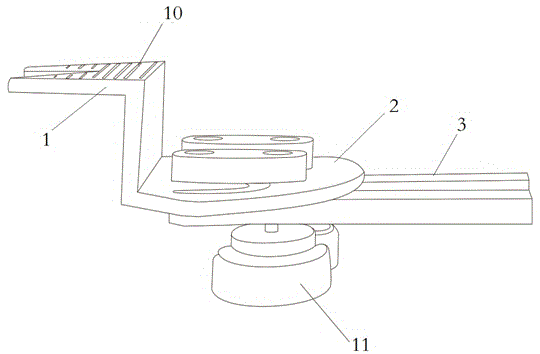
[0034] a base 2,

[0035] A protruding tongue 1 is provided integrally with the base 2, and an anti-skid rail 10 is provided on the tongue 1;

[0036] The rotatable tie rod 3 is connected to the base 2, and the base 2 is provided with a groove 14 for controlling angular rotation, and the rotatable tie rod 3 is fixed in the groove 14 on the base 2 through a rotating mechanism.

[0037] The rotating mechanism includes a slider 12 fixed on the base 2 and a bolt 11 connected with the rotatable tie rod 3,

[0038] The rotatable tie rod 3 is connected to the vertical height rod 5, and the vertical height rod 5 has a scale, and the marking sleeve 4 is set on the vertical height rod 5, and the marking sleeve 5 is reciprocally pulled and pushed on the vertical height rod 5 a...


PUM


Abstract

The invention aims at overcoming the defects in the prior art and providing an oar angle and height positioning device. The oar angle and height positioning device comprises a base and a protruding tongue piece integrally arranged with the base, wherein an anti-slip rail is arranged on the tongue piece. A rotatable tie rod is connected with the base, a groove for controlling angular rotation is formed in the base, the rotatable tie rod is fixed in the groove formed in the base through a rotating mechanism, the rotating mechanism comprises a slide block fixed to the base and a bolt connected with the rotatable tie rod, the rotatable tie rod is connected with a vertical height rod, the vertical height rod is provided with a scale plate and is annularly sleeved with an identifying sleeve, and the identifying sleeve performs longitudinal motion on the vertical height rod with reciprocating push and pull of an oar so as to mark positions. The oar angle and height positioning device is more convenient and accurate and accordingly controls the whole process from action starting to finishing through accurate measurement when a person performs paddling.

Description

technical field [0001] The invention relates to the technical field of speedboat racing equipment, in particular to a paddle angle and height positioning device. Background technique [0002] In the speedboat competition, in addition to the speed of arm paddling frequency and strength, one of the key factors is how much the tail of the oar cuts into the water to achieve better propulsion. If it cuts too deep into the water, the frequency of oar sliding Low, cutting into the water surface is too shallow, and the oars are not strong enough to repel water. The timing of the paddle entering the water and the radian and height of the paddle sliding (one push, one retraction) determine the efficiency of paddling. [0003] In the past, each crew member could only use different materials to make paddle angle positioning devices in their own way, such as cocktail straws, metal wires, wooden sticks, etc. This type of device is crudely made, which is neither convenient nor easy to use...

Claims


Application Information

Patent Timeline
Patent Type & Authority Applications(China)
IPC IPC(8): B63H16/06
CPCB63H16/06
Inventor 马菁
Owner 马菁
Why Eureka
Try Eureka