Engine cooling system with sand strap and control method thereof

A technology of engine cooling and grit chamber, applied in the direction of engine cooling, engine components, machines/engines, etc., can solve the problems of high energy consumption, cumbersome disassembly and maintenance, etc., and achieve low energy consumption, simple disassembly and maintenance, and easy The effect of maintenance

Active Publication Date: 2016-05-04
DONGFENG COMML VEHICLE CO LTD
View PDF10 Cites 1 Cited by
  • Summary
  • Abstract
  • Description
  • Claims
  • Application Information

AI Technical Summary

Problems solved by technology

[0006] The purpose of the present invention is to overcome the defects and problems of high energy consumption and cumbersome disassembly and maintenance in the prior art, and provide an engine cooling system with a grit chamber and its control method with low energy consumption and easy disassembly and maintenance

Method used


Image

  • Engine cooling system with sand strap and control method thereof
  • Engine cooling system with sand strap and control method thereof
  • Engine cooling system with sand strap and control method thereof

Examples


Embodiment 1

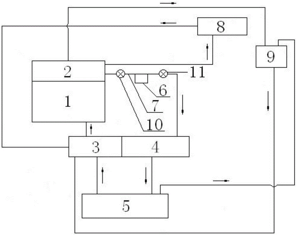
[0047] see figure 1 , an engine cooling system with a grit chamber, including a cylinder water jacket 1, a cylinder head water jacket 2, a water pump 3, the cylinder body water jacket 1 is connected with the cylinder head water jacket 2, and the water outlet of the cylinder head water jacket 2 The water inlet of the radiator 5 is connected through the thermostat 4, and the water outlet of the radiator 5 is connected with the water jacket 1 of the cylinder body through the water pump 3. A grit chamber 6 is arranged on the pipeline 7 between them, and the upper end of the grit chamber 6 communicates with the pipeline 7.

[0048] According to the above scheme, a control method of an engine cooling system with a grit chamber, the control method includes the following steps: the coolant in the water pump 3 passes through the cylinder water jacket 1, the cylinder head water jacket 2, the pipeline 7, the The thermostat 4 and the radiator 5 flow back into the water pump 3; when the c...

Embodiment 2

[0050] Basic content is the same as embodiment 1, the difference is:

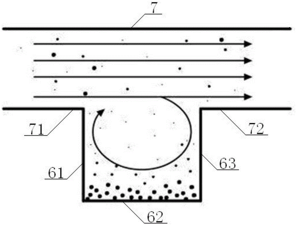
[0051] see figure 2 , image 3 , the grit chamber 6 is a rectangular structure, the grit chamber 6 includes a No. 1 tank side 61, a tank bottom side 62, and a No. 2 tank side 63, and the upper end of the No. 1 tank side 61 is vertically connected with the left lower wall 71 of the pipeline 7, The lower end of the first groove edge 61 is vertically connected with the left end of the groove bottom edge 62, the right end of the groove bottom edge 62 is vertically connected with the lower end of the second groove edge 63, and the upper end of the second groove edge 63 is perpendicular to the lower right wall 72 of the pipeline 7 connection; the outside of the grit chamber 6 is provided with a grit box 64, the No. 1 tank side 61, the tank bottom side 62, and the No. 2 tank side 63 are all located inside the grit box 64, and the No. 1 tank side 61 and the No. 2 tank side The groove edge 63, the left side of th...

Embodiment 3

[0054] Basic content is the same as embodiment 1, the difference is:

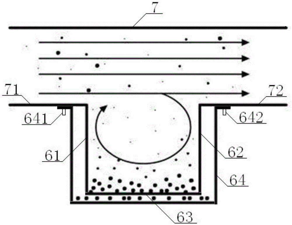
[0055] see Figure 4 , the outside of the grit chamber 6 is provided with a grit box 64, the upper left end of the grit box 64 is connected with the lower left wall 71 of the pipeline 7 through the No. 1 bolt 641, and the upper right end of the grit box 64 is connected with the No. 2 bolt 642 Connected with the lower right wall 72 of the pipeline 7, the grit chamber 6 includes a No. 1 tank side 61 and a No. 2 tank side 63. The No. 1 tank side 61 and the No. 2 tank side 63 are all located inside the grit chamber 64. The upper end of the No. 1 tank side 61 is vertically connected to the left lower wall 71, the upper end of the No. 2 tank side 63 is vertically connected to the right lower wall 72, and the lower ends of the No. 1 tank side 61 and the No. 2 tank side 63 are located above the bottom of the grit chamber 6 , No. 1 groove side 61, No. 2 groove side 63, the left side of the grit chamber 64, and the ...


PUM


Abstract

The invention discloses an engine cooling system with a sand trap. The engine cooling system comprises a cylinder body water jacket, a cylinder cover water jacket and a water pump. The cylinder body water jacket and the cylinder cover water jacket are connected. A water outlet of the cylinder cover water jacket is connected with a water inlet of a radiator through a thermostat. A water outlet of the radiator is connected with the cylinder body water jacket through a water pump. The sand trap is arranged between a pipeline between the water outlet of the cylinder cover water jacket and the water inlet of the thermostat. The upper end of the sand trap is communicated with the pipeline. When cooling liquid enters the pipeline, the cooling liquid containing cylinder cover type sand granule impurities enters the thermostat after passing through the sand trap, and vortex produced through the sand trap enables the cylinder cover type sand granule impurities in the cooling liquid to be deposited at the bottom of the sand trap; then, when an engine is maintained, the bottom of the sand trap is detached to be cleaned, and after cleaning is finished, the bottom of the sand trap is installed, and cooling liquid is added into the engine. The engine cooling system is low in energy consumption, easy and convenient to disassemble and maintain, simple in structure, low in cost and easy to maintain.

Description

technical field [0001] The invention relates to a vehicle engine cooling system, in particular to an engine cooling system with a grit chamber and a control method thereof, which is mainly suitable for reducing particle impurities in the vehicle engine cooling system and protecting the components of the cooling system. Background technique [0002] With the rapid development of the economy, the number of vehicles is increasing. The residual molding sand in the engine cylinder head has a great impact on the reliability and service life of the cooling system components. However, at present, there are few special methods used in the engine cooling system to solve the problem of excessive particulate impurities in the system. Even for a few engines with filter devices, most of them directly use traditional filter media for filtration. The method not only has complicated process and high cost, but also is difficult to arrange so that the particulate impurities can be removed at ...

Claims


Application Information

Patent Timeline
Patent Type & Authority Applications(China)
IPC IPC(8): F01P11/04F01P11/06F01P3/02
CPCF01P3/02F01P11/04F01P11/06F01P2003/028F01P2011/063
Inventor 陈功军
Owner DONGFENG COMML VEHICLE CO LTD
Why Eureka
Try Eureka