An engine cooling system with a grit chamber and its control method
An engine cooling and grit chamber technology, which is applied to engine cooling, engine components, machines/engines, etc., can solve the problems of cumbersome disassembly and maintenance and high energy consumption, and achieve simple disassembly and maintenance, low energy consumption and simple structure. Effect
- Summary
- Abstract
- Description
- Claims
- Application Information
AI Technical Summary
Problems solved by technology
Method used
Image
Examples
Embodiment 1
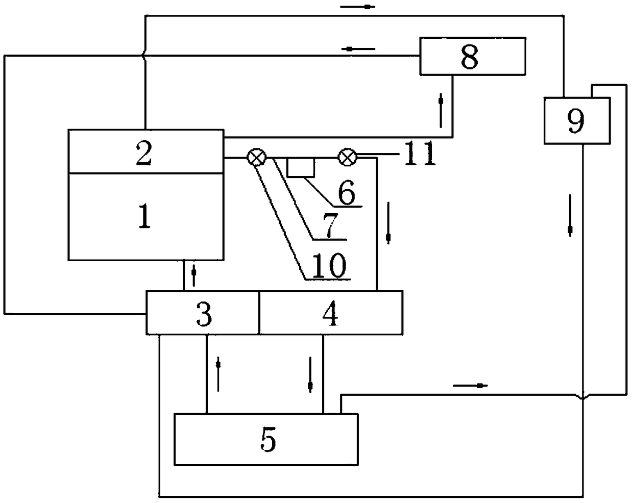
[0047] see figure 1 , an engine cooling system with a grit chamber, including a cylinder body water jacket 1, a cylinder head water jacket 2, a water pump 3, the cylinder body water jacket 1 is connected with the cylinder head water jacket 2, and the water outlet of the cylinder head water jacket 2 The thermostat 4 is connected to the water inlet of the radiator 5, the water outlet of the radiator 5 is connected to the cylinder body water jacket 1 through the water pump 3, and the water outlet of the cylinder head water jacket 2 and the water inlet of the thermostat 4 are connected. A sand settling tank 6 is arranged on the pipeline 7 between the two, and the upper end of the sand settling tank 6 communicates with the pipeline 7 .
[0048] According to the above scheme, a control method of an engine cooling system with a grit chamber, the control method includes the following steps: the cooling liquid in the water pump 3 passes through the cylinder body water jacket 1, the cyl...
Embodiment 2
[0050] The basic content is the same as that of Example 1, except that:
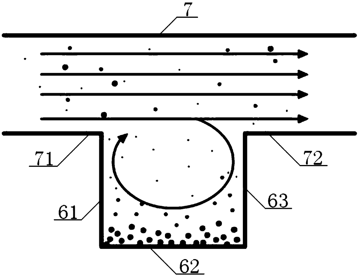
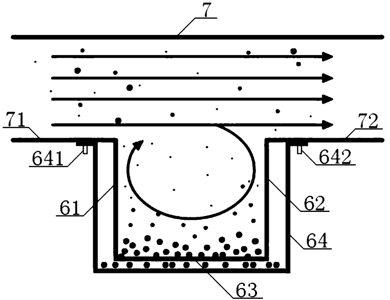
[0051] see figure 2 , image 3 , the sand settling tank 6 is a rectangular structure, and the grit settling tank 6 includes a No. The lower end of the first groove side 61 is vertically connected with the left end of the groove bottom side 62, the right end of the groove bottom side 62 is vertically connected with the lower end of the second groove side 63, and the upper end of the second groove side 63 is perpendicular to the right lower wall 72 of the pipe 7. Connection; the outside of the grit chamber 6 is provided with a grit chamber 64, the first groove edge 61, the groove bottom edge 62, the second groove edge 63 are all located inside the sand chamber 64, the first groove edge 61, the second groove edge 63 The groove edge 63, the left side of the sand settling box 64, and the right side of the sand settling box 64 are all parallel to each other, the bottom edge 62 of the groove is provided with...
Embodiment 3
[0054] The basic content is the same as that of Example 1, except that:
[0055] see Figure 4 , the outer side of the grit chamber 6 is provided with a grit chamber 64, the upper left end of the grit chamber 64 is connected with the lower left wall 71 of the pipeline 7 through the No. 1 bolt 641, and the upper right end of the grit chamber 64 is connected with the second bolt 642 Connected with the lower right wall 72 of the pipeline 7, the sand settling tank 6 includes a No. 1 groove edge 61 and a No. 2 groove edge 63, and the No. 1 groove edge 61 and the No. The upper end of the No. 1 slot edge 61 is vertically connected with the left lower wall 71, the upper end of the No. 2 slot edge 63 is vertically connected with the right lower wall 72, and the lower ends of the No. 1 slot edge 61 and the No. 2 slot edge 63 are located above the bottom of the grit chamber 6. , the No. 1 groove side 61, the No. 2 groove side 63, the left side of the sand settling box 64, and the right ...
PUM
 Abstract
Description
Claims
Application Information
 - R&D
- Intellectual Property
- Life Sciences
- Materials
- Tech Scout
- Unparalleled Data Quality
- Higher Quality Content
- 60% Fewer Hallucinations
Browse by: Latest US Patents, China's latest patents, Technical Efficacy Thesaurus, Application Domain, Technology Topic, Popular Technical Reports.
© 2025 PatSnap. All rights reserved.Legal|Privacy policy|Modern Slavery Act Transparency Statement|Sitemap|About US| Contact US: help@patsnap.com


