
Shrinkage-pipe synthetic-jet valve-less piezoelectric pump

A valveless piezoelectric pump and synthetic jet technology, applied to parts, pumps, pump elements, etc. of pumping devices for elastic fluids, to achieve high flow, large vibration frequency range, and fast response

Inactive Publication Date: 2016-05-04
JIANGSU UNIV
View PDF6 Cites 1 Cited by
  • Summary
  • Abstract
  • Description
  • Claims
  • Application Information

AI Technical Summary

Problems solved by technology

[0005] The purpose of the present invention is to solve the problems existing in the existing synthetic jet valveless pump, and to provide a shrinkable tube synthetic jet valveless piezoelectric pump with a simple structure, a higher velocity when the fluid is ejected, a larger flow rate and continuous flow.

Method used


Image

  • Shrinkage-pipe synthetic-jet valve-less piezoelectric pump
  • Shrinkage-pipe synthetic-jet valve-less piezoelectric pump
  • Shrinkage-pipe synthetic-jet valve-less piezoelectric pump

Examples


Embodiment Construction

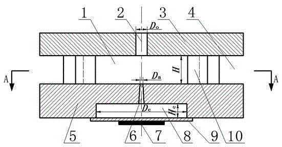
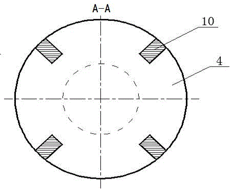
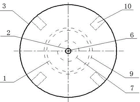
[0016] see figure 1 , figure 2 with image 3 , the present invention includes an upper pump body 3 and a lower pump body 5, the upper pump body 3 is located directly above the lower pump body 5, and the central axes of the two are collinear. Connect the upper pump body 3 and the lower pump body 5 with four columns 10, the upper ends of the columns 10 are fixed on the outer edge of the upper pump body 3, and the upper ends of the columns 10 are fixed on the outer edges of the lower pump body 5. . The four upright columns 10 are evenly arranged along the circumferential direction, and the angle between the centers of every two upright columns 10 is 90 degrees. The gaps between the four columns 10 form the pump inlet 4, which is a circumferential inlet. The space surrounded by four columns 10 , the upper pump body 3 and the lower pump body 5 is the upper chamber 1 . The surrounding fluid enters the upper chamber 1 from the gap pump inlet 4 between the columns 10 .

[0017]...


PUM


Abstract

The invention discloses a shrinkage-pipe synthetic-jet valve-less piezoelectric pump in a micro-fluidic system. Four stand columns are connected to the periphery of the outer edge between an upper pump body and a lower pump body and are evenly arranged in the circumference direction; pump inlets are formed in gaps between the four stand columns, an upper cavity is formed in the space defined by the four stand columns, the upper pump body and the lower pump body, and fluid enters the upper cavity from the pump inlets between the stand columns; a pump outlet communicated with the upper cavity is formed in the middle of the upper pump body, the middle of the lower pump body is provided with a lower cavity and a conical shrinkage spraying pipe located over the lower cavity, the conical shrinkage spraying pipe is communicated with the upper cavity and the lower cavity, and the upper end of the conical shrinkage spraying pipe is a small end, and the lower end of the conical shrinkage spraying pipe is a large end; a vibrating diaphragm is arranged under the bottom of the lower cavity, and a piezoelectric vibrator is bonded to the middle of the lower surface of the vibrating diaphragm. By means of the shrinkage-pipe synthetic-jet valve-less piezoelectric pump, continuous outflow and high-flow outflow can be achieved, and the response speed is high.

Description

technical field [0001] The invention belongs to the technical field of microfluid machinery, microfluid transmission and control, in particular to a valveless piezoelectric micropump in a microfluid system. Background technique [0002] The piezoelectric micropump is the driving element in the microfluidic system, and its performance directly affects the entire microfluidic system. The driving method of the piezoelectric micropump is simple and easy to operate, the precision requirements for processing are relatively low, and the integration degree is high. Achieve miniaturization. Among them, the valveless piezoelectric pump uses a special micro-pipe structure and micro-flow characteristics to realize the operation of the pump, and the structure without a movable valve plate avoids the defects of the valve structure, so it is easier to miniaturize and integrate. [0003] Based on the rapid development of MEMS and the theoretical research on the instability of nonlinear com...

Claims


Application Information

Patent Timeline
Patent Type & Authority Applications(China)
IPC IPC(8): F04B43/04F04B53/00
CPCF04B43/0027F04B43/046F04B53/00
Inventor 何秀华徐梁邓志丹袁寿其
Owner JIANGSU UNIV
Learn More