
A Piezoelectric Micromixer Based on Synthetic Jet

A technology for synthesizing jets and micro-mixers, which is applied in the directions of fluid mixers, mixers, and microstructure devices without moving elements, which can solve the problems of low flow, inability to continuously flow, and large flow resistance.

Inactive Publication Date: 2015-08-26
JIANGSU UNIV
View PDF3 Cites 0 Cited by
  • Summary
  • Abstract
  • Description
  • Claims
  • Application Information

AI Technical Summary

Problems solved by technology

Among them, there are many defects in the micro-mixer: due to the reduction of the scale, the ratio of the fluid surface area to the volume in the micro-channel is quite large, the flow rate and Reynolds number of the liquid are low, and it is often in a state of laminar flow, and the mixing is often at the molecular level. Diffusion motion on the surface makes it difficult to mix trace liquids
[0004] The Chinese patent publication number is CN 102145265 A, the application number is 201110091097.8, and the name is "a piezoelectric microfluidic mixer". Although the disclosed mixer has fast response and high mixing efficiency, its flow rate is low and cannot flow continuously. Large resistance and high energy consumption are not suitable for occasions that require continuous outflow and no backflow
[0005] Existing active micro-mixers are less, and many active micro-mixers are not a complete set of integrated chip structures, but only use extra energy to promote fluid mixing, and still need other power sources, such as syringe pumps to deliver fluids, which It is not conducive to the integration and mass production of chips

Method used


Image

  • A Piezoelectric Micromixer Based on Synthetic Jet
  • A Piezoelectric Micromixer Based on Synthetic Jet
  • A Piezoelectric Micromixer Based on Synthetic Jet

Examples


Embodiment Construction

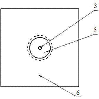
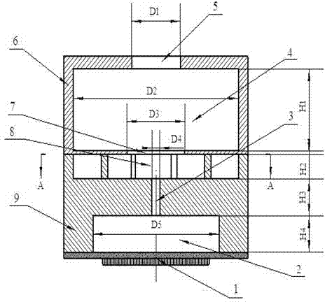
[0016] Such as Figure 1~3 As shown, the present invention includes an upper pump body 6 , a lower pump body 9 , and a piezoelectric vibrator 1 . The upper pump body 6 is directly above the lower pump body 9 and fixedly connected to the lower pump body 9 , and the piezoelectric vibrator 1 is fixed directly below the lower pump body 9 through an adhesive. The piezoelectric vibrator 1 is made of a piezoelectric ceramic sheet glued to the elastic substrate. The piezoelectric vibrator 1 is used as a driving element, using a sinusoidal AC voltage, and the vibration mode adopts radial stretching vibration. The piezoelectric material and the elastic substrate are both circular section.

[0017] There is a pump outlet 5 in the middle of the top surface of the upper pump body 6, and the upper middle of the upper pump body 6 is an upper chamber 4, and the upper chamber 4 communicates with the pump outlet 5. The middle of the lower part of the upper pump body 6 is a confluence area-7, ...


PUM


Abstract

The invention discloses a piezoelectric micromixer, comprising a lower pump body fixedly connected on the right lower of the of an upper pump body, and a piezoelectric vibrator fixed on the right lower of the lower pump body, wherein the a pump outlet is arranged on the right center of the top surface of the upper pump body, the right center of the upper of the upper pump body is an upper cavity, and the right center of the lower of the upper pump body is a confluence area 1; and the right center of the upper of the lower pump body is a confluence area 2 communicated with the confluence area 1, the right center of the lower of the lower pump body is a lower cavity, the cross section of the confluence area 2 is a square, four ribs are arranged on four angles of the square, contours of the cross section of the four ribs are all composed of two parallel log spirals and a section of arc connecting both, two inlets are arranged on each side wall of the confluence 2, and two kinds of fluids respectively and alternantly enter from eight inlets, are primarily mixed by four pre-mixing passages, form a pair of vortexes in the upper cavity, and can implement continuous flux with high amount while mixed.

Description

technical field [0001] The invention relates to the micromechanical field of microfluid mixing and delivery, in particular to a piezoelectric synthetic jet micromixer. Background technique [0002] The microfluidic system can realize the separation, sample addition, mixing, reaction, detection and other functions of the traditional biochemical detection process on the chip. This not only saves reagents, but also reduces dangers (such as toxic or violently reactive reagents). As an emerging technology, microchemical engineering can be used for analysis and comprehensive applications. The microreaction systems involved in microchemical engineering mainly include micromixers, microheat exchangers, and microchannels. Among them, there are many defects in the micro-mixer: due to the reduction of the scale, the ratio of the fluid surface area to the volume in the micro-channel is quite large, the flow rate and Reynolds number of the liquid are low, and it is often in a state of...

Claims


Application Information

Patent Timeline
Patent Type & Authority Patents(China)
IPC IPC(8): B01F5/00B01F5/12B81B1/00B01F25/60
Inventor 何秀华韦丹丹邓志丹杨嵩
Owner JIANGSU UNIV
Learn More