

Active control type inerter
An active control and inerter technology, applied in the field of inerters, can solve problems such as the constant inertia coefficient of the inerter, the inability to adapt to changing vibration input, the limitation of the inertia coefficient of the single flywheel ball screw inerter, etc., to achieve improved Inertia coefficient and the effect of widening the field of use
- Summary
- Abstract
- Description
- Claims
- Application Information
AI Technical Summary
Problems solved by technology
Method used
Image

Examples
Embodiment Construction
[0017] The present invention will be further described below in conjunction with the accompanying drawings and specific embodiments.
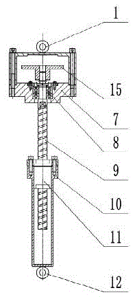
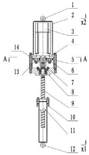
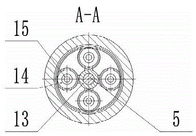
[0018] Such as figure 2 and image 3 As shown, in the active control type inerter of the present invention, the upper hanging ring 1 is fixedly connected to the upper end of the motor casing 2, the lower end of the motor casing 2 is fixedly connected to the upper end of the outer ring gear 4, and the outer shell of the motor 3 is fixedly connected to the upper end of the outer ring gear 4. The motor rotor 5 is fixedly connected to one side of the inner hole of the planet carrier 13 .
[0019] The upper end of the bearing seat 7 is fixedly connected with the outer ring gear 4, the inner hole of the bearing seat 7 is fixedly connected with the outer ring of the bearing group 8, the inner ring of the bearing group 8 is fixedly connected with the screw rod 9, and the screw rod 9 and the nut 11 form a spiral transmission pair.
[0020] The nut 1...
PUM
 Abstract
Description
Claims
Application Information