Differential device and method of manufacturing the same

A technology of a differential device and a manufacturing method, which are applied in the directions of differential transmissions, transmissions, belts/chains/gears, etc., to achieve the effect of preventing burns

Inactive Publication Date: 2016-05-04
MUSA PRECISION IND CO LTD
View PDF7 Cites 0 Cited by
  • Summary
  • Abstract
  • Description
  • Claims
  • Application Information

AI Technical Summary

Problems solved by technology

[0002] In this differential gear, since the input tooth portion (final reduction driven gear) is provided on the outer peripheral portion of the input member, a through hole for supporting the pinion cannot be formed directly below the input tooth portion of the input member.

Method used


Image

  • Differential device and method of manufacturing the same
  • Differential device and method of manufacturing the same
  • Differential device and method of manufacturing the same

Examples


Embodiment Construction

[0026] Hereinafter, embodiments of the present invention will be described with reference to preferred embodiments of the present invention shown in the accompanying drawings.

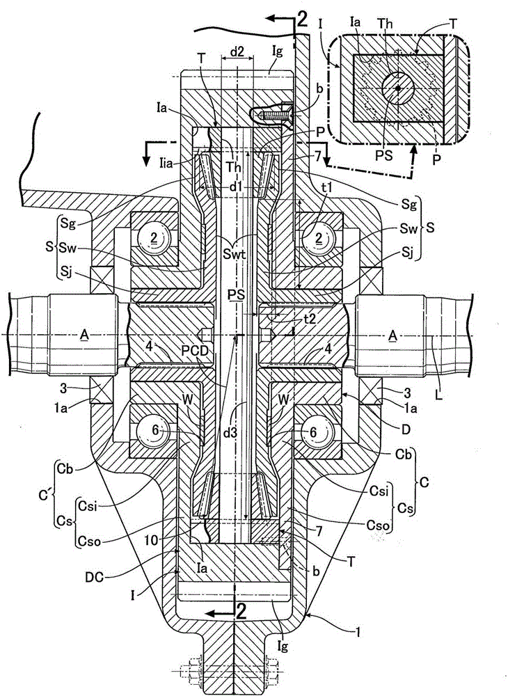
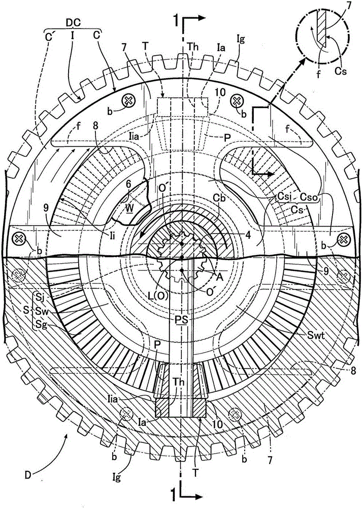
[0027] First, in figure 1 and figure 2 Among them, the differential device D is used to distribute and transmit the rotational drive force transmitted from the engine (not shown) mounted on the automobile to the left and right pair of output shafts A connected to the left and right pair of axles, thereby allowing the left and right The left and right axles are driven while differentially rotating the axles, and the differential device D is housed and supported in, for example, a transmission 1 fixed to the center of the rear part of the vehicle body.

[0028] This differential device D has: a plurality of pinion gears P; pinion gear shaft PS, which is a pinion gear supporting portion that supports these pinion gears P in a rotatable manner; The gear shaft PS supports the pinion shaft PS so as to rot...


PUM


Abstract

In a differential device distributively transmitting rotational force of an input member rotatable together with a pinion support portion to paired output shafts via paired side gears, the support portion is connected to and supported by the input member with high strength without specially forming a through-hole for supporting a pinion in the input member, and without worsening assembly workability. The differential device includes: an attachment body having a retaining hole capable of being fitted and retaining an entire periphery of the pinion support portion; an attachment groove formed in the input member and having an opening opened to one side surface of the input member and from which the attachment body is insertable into the groove; and a cover portion clamping the attachment body inserted into the groove between the cover portion and an inner surface of the groove and fixing the attachment body to the input member.

Description

technical field [0001] The present invention relates to a differential device for distributing and transmitting the rotational force of an input member to a pair of output shafts via a pair of side gears meshing with a pinion, and an improvement in its manufacturing method, wherein the input member holds a small shaft supporting the pinion. The gear support portion is capable of rotating together with the pinion support portion. technical background [0002] In this differential device, since the input tooth portion (final reduction driven gear) is provided on the outer peripheral portion of the input member, a through hole for supporting the pinion cannot be formed directly below the input tooth portion of the input member. Therefore, as shown in Patent Document 1, it is known to form an engaging groove opened on the inner peripheral surface and side surface of the input member, and to directly engage and support the end of the pinion shaft as a pinion support portion on th...

Claims


Application Information

Patent Timeline
Patent Type & Authority Applications(China)
IPC IPC(8): F16H48/38F16H48/08
CPCF16H48/38F16H2048/087F16H2048/382F16H2048/405F16H48/40F16H48/08
Inventor 西村直哉森裕之
Owner MUSA PRECISION IND CO LTD
Why Eureka
Try Eureka