Automatic grease pumping and injecting device and method for bearing lubrication

A bearing lubrication and grease injection device technology, which is applied in the direction of lubricating oil input, lubricating pump, bearing components, etc., can solve the problems of bearing cavity temperature rise, seal leakage, insufficient amount of lubricating grease in the bearing cavity, etc., so as to ensure the safe reserve , to avoid sealing leakage, to ensure the effect of safe lubrication

Active Publication Date: 2016-05-04
HUBEI XINZHI TECH CO LTD
View PDF9 Cites 4 Cited by
  • Summary
  • Abstract
  • Description
  • Claims
  • Application Information

AI Technical Summary

Problems solved by technology

Squeezing out waste lubricating grease by manual or automatic forced replenishment of lubricating grease has three major problems: First, applying pressure to the seal will cause seal leakage, pollute the environment, be difficult to clean, and leave hidden dangers to the safety of equipment maintenance personnel. The second is that the bearing chamber will heat up due to the filling of lubricating grease, resulting in accelerated wear of the bearing and premature deterioration of the lubricating grease; third, the extruded grease will be mixed with a certain amount of new grease, resulting in waste
At present, there is also the practice of liposuction and fat supplementation at the same time. This method cannot achieve equal synchronization of liposuction and fat supplementation, and there are two major shortcomings: first, when the amount of fat injection is greater than the amount of liposuction, the result is the same as the above Like manual or automatic grease injection, the seal will leak due to being squeezed, the temperature of the bearing cavity will rise, and new grease will be drawn out; second, when the amount of liposuction is greater than the amount of grease injected, the amount of grease in the bearing cavity may be insufficient , which poses a threat to the safety of bearing lubrication, and new grease will also be drawn out

Method used


Image

  • Automatic grease pumping and injecting device and method for bearing lubrication

Examples


Embodiment Construction

[0018] The present invention will be described in detail below in conjunction with specific examples, but the protection scope of the present invention is not limited to the following examples.

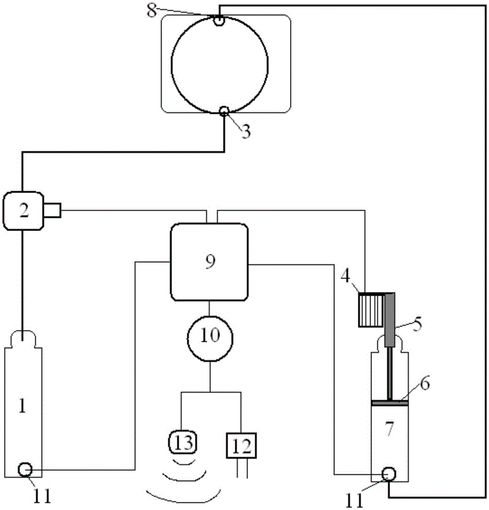
[0019] The structure of the automatic liposuction and grease injection device for bearing lubrication provided by the invention is as follows: figure 1 As shown, including control system, feedback system, liposuction system and fat injection system.

[0020] The liposuction system includes a waste fat storage tank 1, a liposuction pump 2, and pipes, valves, and joints. The liposuction pump 2 is connected to the fat discharge port 3 of the bearing chamber through pipes, joints, and valves, and the outlet of the liposuction pump is connected to the waste fat storage tank. In the same way, the waste grease in the bearing chamber is sucked out from the grease discharge port 3 under the action of the liposuction pump 2 and flows into the waste grease storage tank 1 . The liposuction pump ...


PUM


Abstract

The invention provides an automatic grease pumping and injecting device and method for bearing lubrication. The device at least comprises a control system, a grease pumping system and a grease injecting device; the grease pumping system comprises a waste grease storage tank, a grease pumping pump, a pipe and a connector; the grease injecting device comprises a grease injecting pump, a novel grease storage tank, a pipe and a connector; and the control system comprises a processor, a data storage device and sensors, and the sensors are connected with the grease injecting pump and the grease pumping pump, control closing of the grease injecting pump and the grease pumping pump, are distributed on the novel grease storage tank, the waste grease storage tank and a working site, collect relevant data and transmit the data to the data storage device. The invention further provides the automatic grease pumping and injecting method. According to the technical scheme, the shortcomings in the prior art are overcome; and automatic grease pumping and injecting can be achieved, operation is simple, and the grease pumping amount and the grease injecting amount can be controlled.

Description

technical field [0001] The invention provides an automatic liposuction and grease injection device and method, in particular to an automatic automatic grease suction and grease injection device and method for bearing lubrication, belonging to the technical field of mechanical lubrication. Background technique [0002] In the mechanical field, basically all large-scale mechanical equipment cannot do without bearings, and the rotation of bearings is inseparable from lubrication. Since there is a gap between the rotating shaft and the casing, there is no solid contact, and thermal expansion is allowed, so the grease in the bearing cavity needs to be sealed to prevent the lubricating grease in the bearing cavity from leaking out. The labyrinth seal is to set a number of annular sealing teeth arranged in sequence around the rotating shaft. A series of interception gaps and expansion cavities are formed between the teeth. device for the purpose. Because labyrinth seals are suita...

Claims


Application Information

Patent Timeline
Patent Type & Authority Applications(China)
IPC IPC(8): F16N33/00F16N37/00F16N13/06
CPCF16N13/06F16N33/00F16N37/003F16N2013/063F16N2210/14F16N2270/00
Inventor 邓伦胜
Owner HUBEI XINZHI TECH CO LTD
Why Eureka
Try Eureka