Spinneret detection equipment and method

A detection equipment and detection method technology, applied in the direction of measuring devices, optical testing flaws/defects, instruments, etc., can solve problems such as difficult detection of holes, difficulty in finding the hole, and inability to put forward relevant detection arguments whether the parameters are qualified or not. It is not easy to achieve Leak hole, easy to find holes, realize the effect of automation

Active Publication Date: 2017-12-26
SHANGHAI ACOUSTICS LAB CHINESE ACADEMY OF SCI
View PDF6 Cites 1 Cited by
  • Summary
  • Abstract
  • Description
  • Claims
  • Application Information

AI Technical Summary

Problems solved by technology

The bottom irradiation method of strong light source can only observe whether the holes on the entire board surface are transparent and whether there are holes blocked. It is easy to miss inspection, and it is impossible to find small dirt in the holes, and it is impossible to quantify the data of the microholes.
Compared with visual inspection, inspection under a microscope can enlarge the hole and observe the fine dirt in the hole. However, since the carbon fiber spinneret has tens of thousands of micropores, and the distance between the holes is only less than 100 μm , so missed detection is very easy to happen, even if dirt is detected in a certain hole, it is difficult to find this hole on the spinneret
In addition, the surface of some wet spinning spinnerets is an arc surface, and the direction of the hole is consistent with the normal direction of the arc surface. The detection under the microscope needs to be continuously adjusted. When the angle difference between the direction of the hole and the detection direction of the eyepiece is too large, the hole difficult to detect
Similarly, this detection method cannot provide relevant detection arguments for whether the parameters of the hole are qualified.

Method used


Image

  • Spinneret detection equipment and method
  • Spinneret detection equipment and method

Examples


Embodiment Construction

[0034] In order to make the above objects, features and advantages of the present invention more comprehensible, specific implementations of the present invention will be described in detail below in conjunction with the accompanying drawings.

[0035] In the following description, numerous specific details are set forth in order to provide a thorough understanding of the present invention. However, the present invention can be implemented in many other ways different from those described here, and those skilled in the art can make similar extensions without violating the connotation of the present invention, so the present invention is not limited by the specific implementations disclosed below.

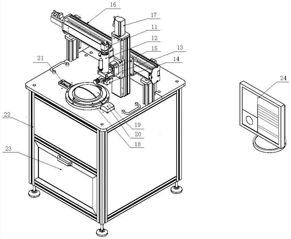
[0036] figure 1 The spinneret detection equipment according to the embodiment of the present invention is shown, including: camera devices (11 and 12), a horizontal rotary table 18, a laser ranging sensor 14 and a detection control device 24.

[0037] The imaging device is arranged...


PUM


Abstract

The invention provides spinneret plate detection equipment, and the equipment comprises a camera device which is disposed above a spinneret plate placement plane, and is used for photographing the spinneret plate; a horizontal rotating platform which is provided with a placement part for placing the spinneret plate, and can enable the spinneret plate to rotate on the placement plane; a laser distance measurement sensor which is disposed above the spinneret plate placement plane, can move horizontally and is used for detecting the surface distance of the spinneret plate; and a detection control device which receives the surface distance, measured by the laser distance measurement sensor, of the spinneret plate, and adjusts the photographing angle of the camera device according to the surface distance of the spinneret plate. The photographing angle enables a photographing plane to be roughly parallel to a tangent plane of a spinneret plate detection point. The detection control device receives a spinneret plate image of the camera device, so as to measure a spinneret plate micropore. The equipment cannot cause detection leakage of the spinneret plate micropore.

Description

technical field [0001] The invention relates to spinneret detection technology, in particular to automatic spinneret detection equipment and method. Background technique [0002] Carbon fiber has excellent properties unmatched by other fibers in special application fields such as high strength, light weight, high temperature resistance, and corrosion resistance. It is a high-tech material for both military and civilian purposes. (Manufacture of Shenzhou spacecraft and large aircraft), national defense technology (missile) and other national high-tech strategic projects all have huge demand for carbon fiber. In my country, there are currently more than 40 large and small enterprises producing carbon fiber, with a total production capacity of 16,000-20,000 tons. However, due to the lack of core technology, the actual output of carbon fiber in my country is only about 2,000 tons. The manufacturing process of carbon fiber is generally made of polyacrylonitrile fiber (PAN), pit...

Claims


Application Information

Patent Timeline
Patent Type & Authority Patents(China)
IPC IPC(8): G01B11/24G01N21/94
CPCG01B11/24G01N21/94
Inventor 周红生靳小尨王晓庆周斌王欢
Owner SHANGHAI ACOUSTICS LAB CHINESE ACADEMY OF SCI
Why Eureka
Try Eureka