Rapid maintenance device for pneumatic conveying of material and material pneumatic conveying system

A technology of pneumatic conveying and rapid maintenance, applied in the direction of analyzing materials, instruments, etc., can solve the problems of lagging maintenance work, difficult operator stuck positions, and high maintenance costs, so as to improve work efficiency, fast maintenance operations, and reduce difficulty and cost. Effect

Active Publication Date: 2016-05-04
HUNAN SUNDY SCI & TECH DEV
View PDF4 Cites 0 Cited by
  • Summary
  • Abstract
  • Description
  • Claims
  • Application Information

AI Technical Summary

Problems solved by technology

[0005] (1) The existing technology cannot monitor the operation of the object to be conveyed in the transmission pipeline in real time. When an object to be conveyed is stuck in the transmission pipeline, the transmission system or the operator cannot promptly and quickly discover the stuck object to be conveyed, resulting in maintenance lag
This has seriously affected the normal delivery of samples and the development of follow-up work
In severe cases, it may even lead to continuous jamming and backlog of multiple items to be transported in the transmission pipeline
[0006] (2) Since the pneumatic transmission pipeline is very long (maybe hundreds of meters), and the pipeline is very small (people cannot enter), it is very difficult for the operator to obtain the specific stuck position once the material to be conveyed is stuck in the transmission pipeline of
This further makes it very difficult to unclog the stagnation, the maintenance cycle is long, and the maintenance cost is extremely high
[0007] (3) In the existing technology, when it is found that the object to be conveyed is stuck in the transmission pipeline, the stuck problem is solved by sending an object to be conveyed in reverse and pushing the stuck object back to the sending position. When the transportation distance is long, there is a backlash weakness, which leads to the need to forcibly disassemble and cut the transmission pipeline to remove the stuck and waiting goods. This method makes the maintenance work cycle long and serious. Affects the maintainability and economics of operation of transmission pipelines

Method used


Image

  • Rapid maintenance device for pneumatic conveying of material and material pneumatic conveying system
  • Rapid maintenance device for pneumatic conveying of material and material pneumatic conveying system
  • Rapid maintenance device for pneumatic conveying of material and material pneumatic conveying system

Examples


specific Embodiment 1

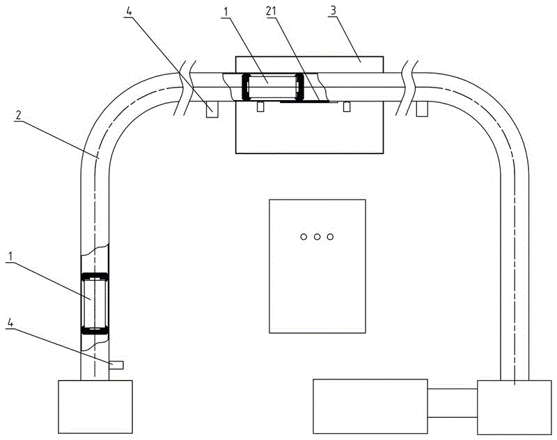
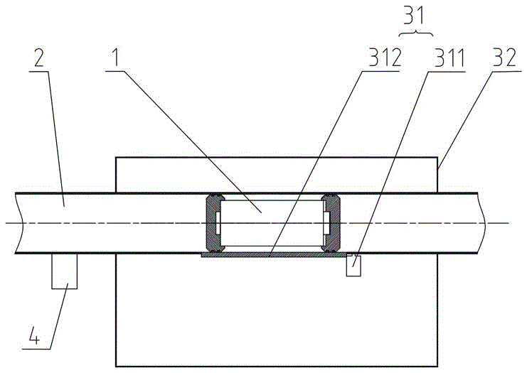
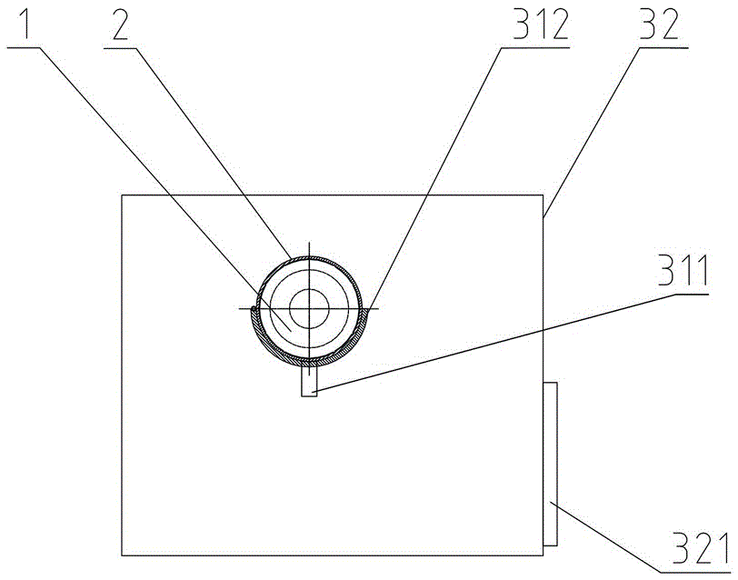
[0036] Specific embodiment 1: as Figure 2 to Figure 4 As shown, in this embodiment, the retaining plate 312 is hinged to the pneumatic transmission pipe 2 , and the retaining plate 312 is turned downwards to open the retaining port 21 under the drive of the retaining drive member 311 . When the operation monitoring unit 4 detects no abnormality, the retaining plate 312 blocks the retaining port 21 under the drive of the retaining drive member 311 , so that the object 1 to be conveyed can quickly pass through the retaining port 21 for pneumatic transmission. Once it is detected that there is an abnormal situation in the object to be conveyed 1 and needs to be intercepted, the interception drive member 311 drives the interception plate 312 to turn down so that the interception port 21 is opened, so that the object to be transported 1 to be passed falls from the interception port 21 to the interception port. Inside the main body 32 of the maintenance box.

specific Embodiment 2

[0037] Specific embodiment 2: as Figure 5 , Image 6 As shown, in this embodiment, the retaining drive member 311 includes a lifting screw assembly connected with the retaining plate 312 , and the lifting screw assembly drives the retaining plate 312 up and down to open / close the retaining port 21 . The lifting screw assembly can be arranged directly under the retaining plate 312 , or can be arranged on both sides above the retaining plate 312 as shown in the figure.

[0038] Such as Figure 1 to Figure 6 As shown, further, in a preferred embodiment, the operation monitoring unit 4 includes a level monitoring sensor assembly, which is arranged on the pneumatic transmission pipeline 2 for monitoring the moving speed of the object 1 to be transported in the pipeline. The level monitoring sensor assembly includes two or more level monitoring sensors, and there is a certain distance a between the two or more level monitoring sensors. When more than two level monitoring sensors...


PUM


Abstract

The invention discloses a rapid maintenance device for pneumatic conveying of materials. The rapid maintenance device comprises an operation monitoring unit and an interception maintenance unit which are matched with each other, wherein the operation monitoring unit is arranged on a pneumatic conveying pipeline and is used for monitoring a conveying state of materials to be conveyed in the pneumatic conveying pipeline in real time; the interception maintenance unit is in sealing connection with the pneumatic conveying pipeline; a material-to-be-conveyed interception assembly is arranged on the interception maintenance unit; the material-to-be-conveyed interception assembly is used for intercepting the materials to be conveyed, that are conveyed abnormally, at the interception maintenance unit for performing a maintenance operation according to real-time monitoring information of the operation monitoring unit. The invention further discloses a material pneumatic conveying system. The rapid maintenance device and the material pneumatic conveying system disclosed by the invention have the advantages that the conveying situation of the materials to be conveyed in the pneumatic conveying pipeline can be monitored in real time, and the abnormal materials to be conveyed can be obtained in time, such that the maintenance operation is rapid and timely, as well as economic and efficient.

Description

technical field [0001] The invention mainly relates to the field of equipment for collecting and processing material samples, and in particular to a quick maintenance device and a material pneumatic conveying system for pneumatic conveying of materials. Background technique [0002] For the sampling, sample preparation, and testing of material (such as ore, coal) samples, each country has mandatory standards, and the sampling and processing of samples must be carried out in accordance with the standards. The principle of sample sampling, sample preparation, and testing work process is to gradually reduce the particle size and quality of the collected samples without destroying the representativeness of the sample, until it meets the particle size and quality of the sample in the laboratory test ( Weight) accuracy requirements, and then carry out relevant laboratory analysis on the samples that meet the requirements. [0003] For example, taking coal sampling as an example, ...

Claims


Application Information

Patent Timeline
Patent Type & Authority Applications(China)
IPC IPC(8): G01N35/00
CPCG01N35/00
Inventor 任率朱青刘清海王芹
Owner HUNAN SUNDY SCI & TECH DEV
Why Eureka
Try Eureka