
Waveform triggering device and method and oscilloscope for waveform triggering

A waveform triggering and oscilloscope technology, applied in the direction of digital variable/waveform display, measuring devices, instruments, etc., can solve the problems of weak ability to suppress noise, harmonics, and inaccurate trigger position, etc., and achieve the effect of high trigger accuracy

Inactive Publication Date: 2016-05-04
INNO INSTR (CHINA) INC
View PDF7 Cites 4 Cited by
  • Summary
  • Abstract
  • Description
  • Claims
  • Application Information

AI Technical Summary

Problems solved by technology

[0003] However, due to the presence of noise and harmonics in the input signal, the trigger device of a traditional digital oscilloscope only uses a trigger comparator, which easily leads to false triggering; or uses a hysteresis comparator. If the hysteresis range is relatively small, the ability to suppress noise will be reduced. Weaker, and if the hysteresis range is relatively large, the trigger position will not be accurate enough
At present, there is no waveform trigger technology that has a high ability to suppress noise and does not affect the accuracy of the trigger position.

Method used


Image

  • Waveform triggering device and method and oscilloscope for waveform triggering
  • Waveform triggering device and method and oscilloscope for waveform triggering
  • Waveform triggering device and method and oscilloscope for waveform triggering

Examples


Embodiment Construction

[0027] In order to make the above objects, features and advantages of the present invention more comprehensible, specific implementations of the present invention will be described in detail below in conjunction with the accompanying drawings.

[0028] In the following description, numerous specific details are set forth in order to provide a thorough understanding of the present invention. However, the present invention can be implemented in many other ways different from those described here, and those skilled in the art can make similar extensions without violating the connotation of the present invention, so the present invention is not limited by the specific implementations disclosed below.

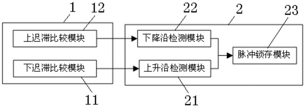
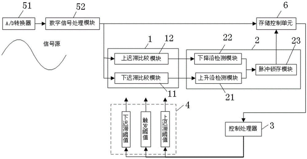
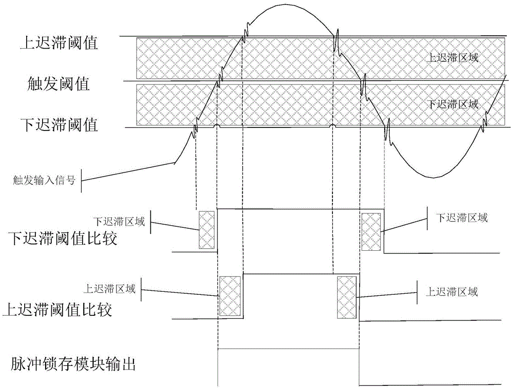
[0029] figure 1 The waveform trigger device according to the embodiment of the present invention includes a comparison unit 1 and a detection output unit 2 . Wherein, the comparison unit 1 comprises a lower hysteresis comparison module 11 and an upper hysteresis comparison module 1...


PUM


Abstract

The invention provides a waveform triggering device. A comparison unit comprises a lower retardation comparison module and an upper retardation comparison module which receive triggering input signals simultaneously, the lower retardation limit of the lower retardation comparison module is lower than that of the upper retardation comparison module, the upper retardation limit of the lower retardation comparison module is greater than or equivalent to the lower retardation limit of the upper retardation comparison module, the upper retardation limit of the lower retardation comparison module is lower than that of the upper retardation comparison module, the lower retardation comparison module outputs first pulse signals, and the upper retardation comparison module outputs second pulse signals. A rising edge detection module receives the first pulse signals and outputs pulse rising edge detection signals in response to the rising edge of the first pulse signals; a falling edge detection module receives the second pulse signals and outputs pulse falling edge detection signals in response to the falling edge of the second pulse signals, and the pulse rising edge detection signals and the pulse falling edge detection signals are used for controlling formation of waveform triggering signals. According to the invention, the influence of signal noise on the triggering signals is lowered greatly, and accurate waveform triggering is supported.

Description

technical field [0001] The invention belongs to the technical field of electronic signal processing, and in particular relates to a waveform triggering device, an oscilloscope and a waveform triggering method capable of realizing precise waveform triggering. Background technique [0002] Oscilloscopes have been widely used in various fields of test and measurement. The circuit design of the digital oscilloscope is small and easy to carry, and the digital oscilloscope is more and more favored by everyone because of its easy operation and high stability. In test and measurement, higher requirements are put forward for the measurement accuracy of digital oscilloscopes. Whether it is an analog oscilloscope or a digital oscilloscope, obtaining an accurate waveform trigger signal is of great significance to improving measurement accuracy. [0003] However, due to the presence of noise and harmonics in the input signal, the trigger device of a traditional digital oscilloscope onl...

Claims


Application Information

Patent Timeline
Patent Type & Authority Applications(China)
IPC IPC(8): G01R13/02
CPCG01R13/0209
Inventor 李楚元
Owner INNO INSTR (CHINA) INC
Learn More