Single skeleton for winding multiple optical fibers, and application method of single skeleton

An optical fiber and skeleton technology, which is applied in the field of multi-segment optical fiber loop coiling, can solve the problems that restrict the wide use of optical fiber delay loops, deteriorate the performance of optical fiber delay loops, and cannot coil multi-segment optical fibers, achieve good temperature environment adaptability, and improve the temperature environment. Adaptability, the effect of improving coiling efficiency

Active Publication Date: 2016-05-04
CHINA ELECTRONICS TECH GRP NO 23 RES INST
View PDF6 Cites 8 Cited by
  • Summary
  • Abstract
  • Description
  • Claims
  • Application Information

AI Technical Summary

Problems solved by technology

[0003] However, the current optical fiber coiling technology cannot directly coil multiple segments of optical fiber on a single backbone
For example, after winding the first section of optical fiber, and then coiling the second section of optical fiber directly on it, the second section of optical fiber will squeeze the pigtail of the first section of optical fiber, which will cause the insertion loss of the first section of delay fiber to change. If the third fiber is coiled directly on the second fiber, the third fiber will squeeze the pigtail of the second fiber, resulting in the insertion loss of the second delayed fiber become larger or even the pigtail breaks
[0004] In addition, since the frame of the commonly used fiber delay ring is made of metal, when the ambient temperature changes, the expansion performance mismatch between the fiber coil and the metal frame will cause the performance of the fiber delay ring to deteriorate, thereby restricting the performance of the fiber delay ring. the widespread use of

Method used


Image

  • Single skeleton for winding multiple optical fibers, and application method of single skeleton
  • Single skeleton for winding multiple optical fibers, and application method of single skeleton
  • Single skeleton for winding multiple optical fibers, and application method of single skeleton

Examples


Embodiment 1

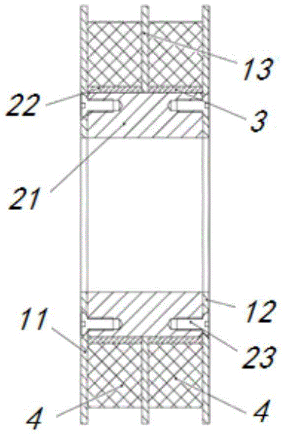
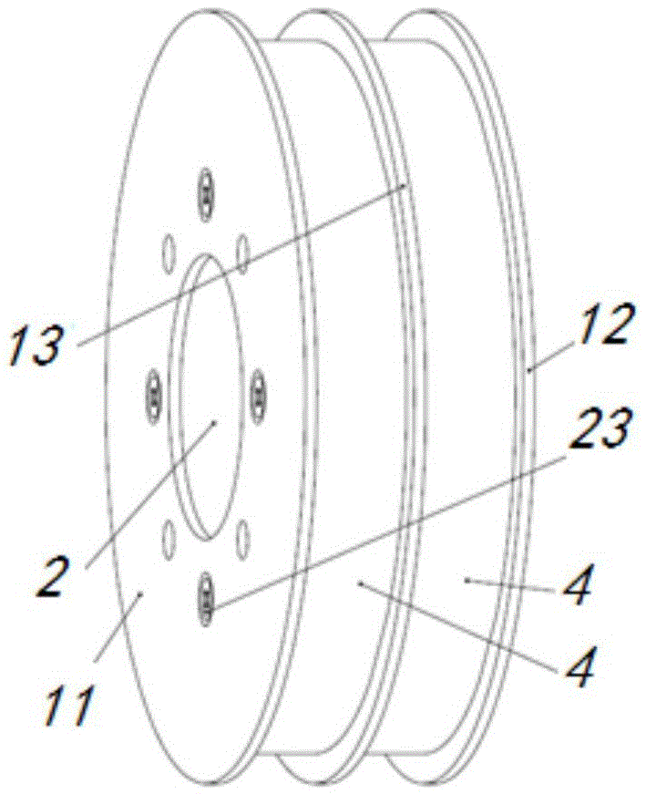
[0036] Such as figure 1 and figure 2 As shown, a single frame for coiling multiple segments of optical fibers in Embodiment 1 includes a baffle plate 1 , a winding shaft 2 and a supporting sleeve 3 .

[0037] The baffles in Embodiment 1 include: a first outer baffle 11 , a second outer baffle 12 and an intermediate baffle 13 located between the first outer baffle 11 and the second outer baffle 12 .

[0038] This embodiment 1 takes an intermediate baffle 13 as an example to illustrate the structure of the single skeleton in the present invention, so as to facilitate the understanding of the technology in the present invention. According to the number of coils of the optical fiber ring 4, multiple intermediate baffles can be added 13 to coil a plurality of optical fiber rings 4.

[0039] The separate structure of the winding shaft 2 in the first embodiment is mainly manifested in that one end surface of the winding shaft 2 and the inner side of the first outer baffle plate 11...

Embodiment 2

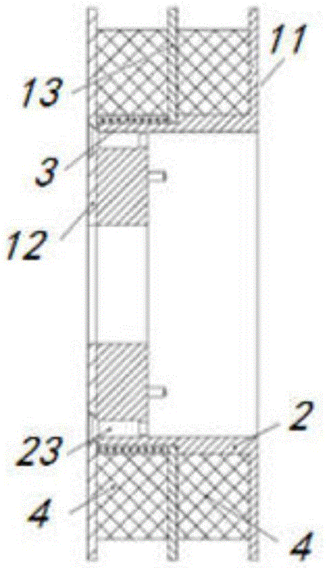
[0042] Such as image 3 and Figure 4 As shown, a single frame for coiling multiple segments of optical fibers in Embodiment 2 includes a baffle 1 , a winding shaft 2 and a supporting sleeve 3 .

[0043] The baffles in the second embodiment include: a first outer baffle 11 , a second outer baffle 12 and an intermediate baffle 13 located between the first outer baffle 11 and the second outer baffle 12 .

[0044] This embodiment 2 takes an intermediate baffle 13 as an example to illustrate the structure of the single skeleton in the present invention, so as to facilitate the understanding of the technology in the present invention. According to the number of coils of the optical fiber ring 4, multiple intermediate baffles can be added 13 to coil a plurality of optical fiber rings 4.

[0045] The integral structure of the winding shaft 2 in the second embodiment is mainly manifested in that one end surface of the winding shaft 2 and the inner side of the first outer baffle 11 a...


PUM


Abstract

The invention discloses a single skeleton for winding multiple optical fibers, and the skeleton comprises baffle plates, a winding shaft, and a supporting sleeve. The baffle plates comprises a first baffle plate, a second baffle plate, and at least one central baffle plates located between the first and second baffle plates. The invention also discloses a method for winding multiple optical fibers through the skeleton, and comprises six steps. Through the six steps, the method achieves the quick winding, makes reasonable use of the space of the skeleton, improves the environment adaptability of the optical fibers, and enables the skeleton to have good temperature environment adaptability. The skeleton can achieve the winding of multiple optical fibers thereon, and the adjacent optical fibers are isolated through the baffle plates. Moreover, the limited space is used reasonably, and the size is reduced.

Description

technical field [0001] The invention relates to a single framework for coiling multi-segment optical fiber rings, and a method for coiling multi-segment optical fiber rings using the single framework. Background technique [0002] The wavelength division multiplexing system uses optical signals of multiple wavelengths to realize communication. When multiple signals arrive at the same receiving end through channels with different optical paths, in order to synchronize the optical signals of each channel, it is necessary to access Fiber delay loops with different fiber lengths are implemented. Under the condition of unlimited structure, multiple fiber delay loops with skeletons can be connected in the system, but in the case of limited volume, it is necessary to consider saving space and adopt the structural form of multiple delay coils coiled on a single skeleton. . [0003] However, the current optical fiber coiling technology cannot directly coil multiple segments of opti...

Claims


Application Information

Patent Timeline
Patent Type & Authority Applications(China)
IPC IPC(8): G02B6/44
Inventor 柳吉铭郭葆玲李斌宋承盈
Owner CHINA ELECTRONICS TECH GRP NO 23 RES INST
Why Eureka
Try Eureka