Hook type connecting and unlocking device

An unlocking device and unlocking technology, which is applied to projectiles, self-propelled projectiles, offensive equipment, etc., can solve the problem that the belt-type separation device has a large separation impact, is not conducive to improving the reliability of the launch vehicle, and is difficult to control the uniformity of the preload force distribution. and other problems, to achieve the effect of improving separation reliability, effective connection method, and uniform force

Active Publication Date: 2018-03-30
BEIJING INST OF ASTRONAUTICAL SYST ENG +1
View PDF6 Cites 2 Cited by
  • Summary
  • Abstract
  • Description
  • Claims
  • Application Information

AI Technical Summary

Problems solved by technology

Since the work of the explosive bolt or cutter is to achieve material fracture within a few hundred microseconds, the pre-tightening force of the tape and the strain energy of the docking frame are also released instantly, and the separation impact of the tape-type separation device is too large. Hazards to rocket safety
At the same time, since the separated pyrotechnic components such as explosive bolts or cutters cannot be reused after working once, the unlocking and separation of the tape cannot be pre-detected on the ground, which is not conducive to improving the reliability of the launch vehicle
In addition, the distribution uniformity of the pre-tightening force generated when the tape is loaded is not easy to control. Repeated trial installation and partial knocking are required to make the pre-tightening force evenly distributed as much as possible, which leads to cumbersome installation operations and low efficiency.
The pre-tightening force of the thin tape is greatly affected by the ambient temperature. The influence of temperature needs to be considered during the design and use process, and a certain margin must be taken to ensure the connection stiffness. This will have a negative impact on the environment and installation operations that the tape is allowed to use.

Method used


Image

  • Hook type connecting and unlocking device
  • Hook type connecting and unlocking device
  • Hook type connecting and unlocking device

Examples


Embodiment Construction

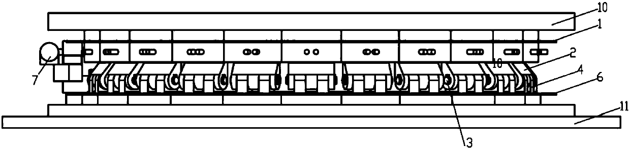
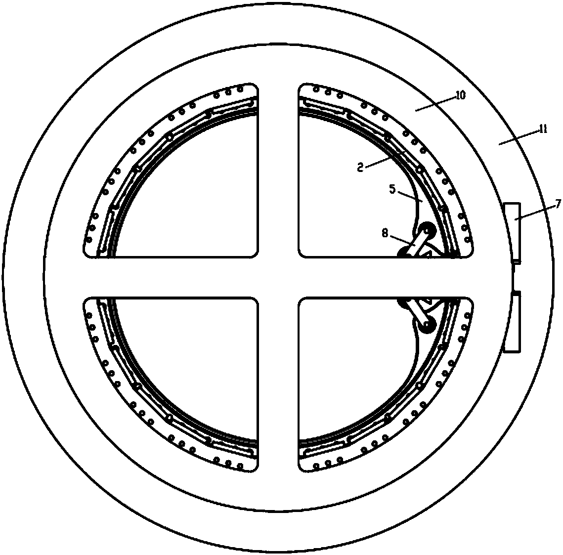
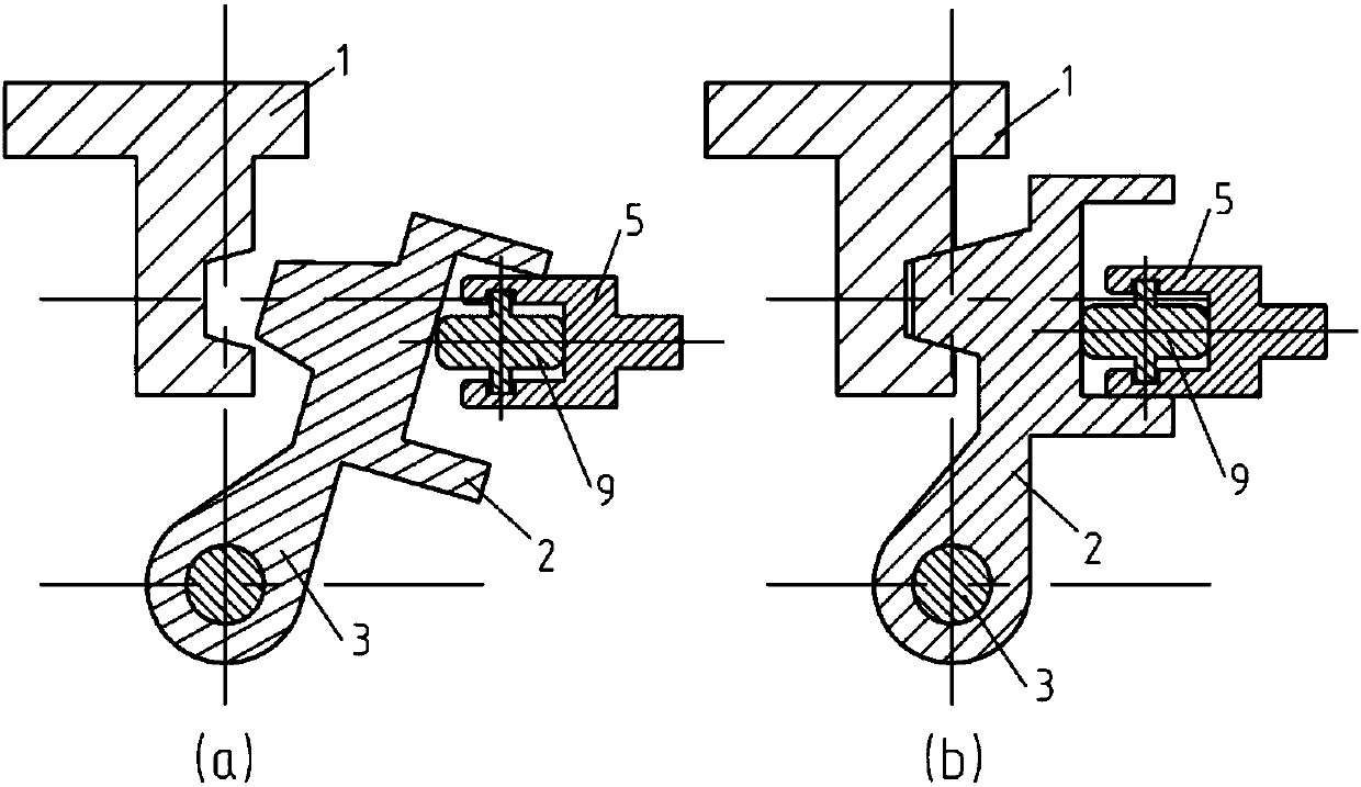
[0036] The purpose of the present invention is to disclose a separation method between stages and even satellites that can meet the separation requirements of space vehicles. The present invention will be described in detail below in conjunction with the accompanying drawings and examples. Such as figure 1 As shown, the structure of the hook-type connection and unlocking device mainly includes an upper frame 1, a rotating block 2, a roller 3, a base 4, an inner support ring 5, a lower frame 6, a motor assembly 7, a connecting rod 8 and a roller 9.

[0037] Wherein the upper end frame 1 is fixed together with the structural member 10 through the upper butt joint fastener, the lower end frame 6 is fixed together with the structural member 11 through the lower butt joint fastener, and the rotating block 2 is connected with the base 4 through the roller 3, The base 4 is fixed on the lower end frame 6 by fasteners, the inner support ring 5 is placed in the U-shaped groove of the ro...


PUM


Abstract

A hook type connecting and unlocking device comprises an upper end frame (1), a rotating block (2), a rolling shaft (3), a base (4), an internal supporting ring (5), a lower end frame (6), a motor assembly (7), connecting rods (8) and a roller (9), wherein the upper end frame (1) and the lower end frame (6) are separately fixedly connected to two structures (10 and 11) to be connected and unlocked; a groove is formed in the upper end frame (1); the lower end frame (6) is fixedly connected with the base (4); one end of the rotating block (2) is connected to the base (4) through the rolling shaft (3); a projection is arranged on one side of the other end of the rotating block (2); the shape of the projection is matched with that of the groove; a slot is formed in the other side of the otherend of the rotating block (2); the internal supporting ring (5) is placed in the slot and is connected with the motor assembly (7) through the connecting rods (8); and under the driving effect of themotor assembly (7), the projection on the rotating block (2) rotates around the rolling shaft (3) to enter the groove of the upper end frame (1) or leave away from the groove of the upper end frame (1) through expansion and shrinkage of the internal supporting ring (5), and thus, locking and releasing of the two structures (10 and 11) are realized.

Description

technical field [0001] The invention belongs to the technical field of launch vehicle structures, and in particular relates to a device capable of realizing effective connection and unlocking between two structural parts. Background technique [0002] The interstage and payload separation devices of launch vehicles are mainly divided into three types: wired type, point type and combined type separation. Typical line separation devices include flexible detonating cord, shaped energy cutting cord separation device, expansion tube separation device and airbag separation device, etc. Typical point separation devices include explosive bolts, explosive nuts, separation nuts, etc. The combined separation device is mainly a tape separation device. However, the existing separation devices all use pyrotechnic devices as the action energy, which has the disadvantages of large impact, undetectable and undetectable before use, and also has certain safety problems. For example, the wra...

Claims


Application Information

Patent Timeline
Patent Type & Authority Applications(China)
IPC IPC(8): F42B15/36
Inventor 吴晗玲曲展龙张志峰宋保永唐科于兵胡振兴苏晗陈岱松李岩赵崇斌王迪赫志亮张乔飞黄诚刘靖东谷立祥
Owner BEIJING INST OF ASTRONAUTICAL SYST ENG
Why Eureka
Try Eureka