Lambert map projection presentation device and method
A demonstration device and map projection technology, applied in the directions of maps/plans/charts, planetariums/globes, instruments, etc., can solve problems such as poor teaching effect, and achieve the effect of improving teaching effect, simple design and production, and convenient material selection.
- Summary
- Abstract
- Description
- Claims
- Application Information
AI Technical Summary
Problems solved by technology
Method used
Image
Examples
Embodiment 1
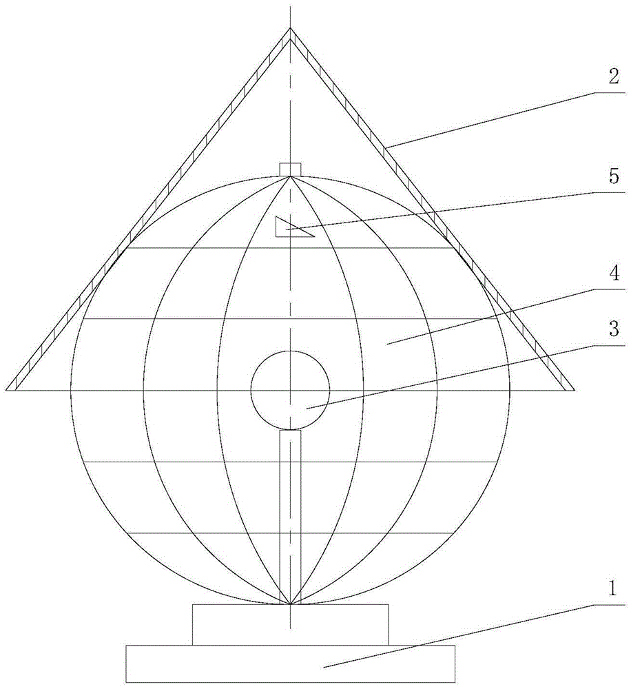
[0019] Such as figure 1 As shown, the Lambert map projection demonstration device of this embodiment is composed of a base 1 , a perspective paper cover 2 , a light bulb 3 , a globe main body 4 and a deformation verification triangle 5 .
[0020] Specifically: the base 1 of the present embodiment adopts an ordinary desk lamp base 1, and a light bulb 3 is installed on the base 1, and a globe main body 4 is also installed outside the light bulb 3, and the light bulb 3 is installed at the center of the earth of the globe main body 4. The main body 4 of the globe is composed of a globe skeleton and a polyester film with good light transmission, wherein the globe skeleton is a simple globe skeleton that is lapped with thin iron wires according to the longitude and latitude lines to form a spherical mesh structure, the bottom is fixed on the base 1, and the top is Use pins to fix the joints of the overlapped thin iron wires. The top of the globe frame is fixed with pins. The size is...
Embodiment 2
[0029] The deformation verification triangle of this embodiment is an equilateral triangle with a side length of 20mm, and its sticking position is on the lower hemispherical surface close to the South Pole.
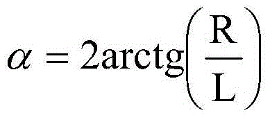
[0030] Satisfy between the busbar length l of the perspective drawing cover 2 of the present embodiment and the equatorial radius R of the globe main body 4:
[0031] α = 2 a r c t g ( R l )
[0032] Wherein α is the cone angle of the transparent paper cover 2, α=75°.
[0033] The other components and their mounting configurations are the same as in Embodiment 1.
Embodiment 3
[0035] The deformation verification triangle in this embodiment is an equilateral triangle with a side length of 20 mm, and its sticking position is on the upper hemispherical surface close to the North Pole.
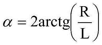
[0036] Satisfy between the busbar length l of the perspective drawing cover 2 of the present embodiment and the equatorial radius R of the globe main body 4:
[0037] α = 2 a r c t g ( R 1 )
[0038] Wherein α is the cone angle of the transparent paper cover 2, α=30°.
[0039] The other components and their mounting configurations are the same as in Embodiment 1.
[0040] In the foregoing embodiment, the deformation verification triangle 5 can be adjusted in position according to the actual situation, and the angle of the triangle can also be adjusted appropriately. In the same way, the longitude and lat...
PUM
 Abstract
Description
Claims
Application Information
 - R&D
- Intellectual Property
- Life Sciences
- Materials
- Tech Scout
- Unparalleled Data Quality
- Higher Quality Content
- 60% Fewer Hallucinations
Browse by: Latest US Patents, China's latest patents, Technical Efficacy Thesaurus, Application Domain, Technology Topic, Popular Technical Reports.
© 2025 PatSnap. All rights reserved.Legal|Privacy policy|Modern Slavery Act Transparency Statement|Sitemap|About US| Contact US: help@patsnap.com


