
Key structure

A key and positioning structure technology, applied in tactile feedback, electrical components, electric switches, etc., can solve the problems of poor life and elastic characteristics, difficult implementation, etc., to reduce frictional resistance, save installation space, and compact structure Effect

Active Publication Date: 2016-05-04
DARFON ELECTRONICS (SUZHOU) CO LTD +1
View PDF5 Cites 4 Cited by
  • Summary
  • Abstract
  • Description
  • Claims
  • Application Information

AI Technical Summary

Problems solved by technology

However, with the trend of thinner keyboards, when the height of the keyboard’s up and down movement is required to be reduced, the height of the bowl-shaped rubber body must also be reduced. However, when the height of the bowl-shaped rubber body is reduced, the characteristics of life and elasticity will deteriorate.
In addition, for longer keys (also known as multiple keys), usually a plurality of connecting rods are arranged at the bottom of the key cap so that when the user presses any position on the key cap, it can indeed keep moving up and down horizontally and allow the user to feel To achieve a clear resilience (or feel), but as the height of the keyboard is required to be lowered, due to space constraints, this design is not easy to implement

Method used


Image

  • Key structure
  • Key structure
  • Key structure

Examples


Embodiment Construction

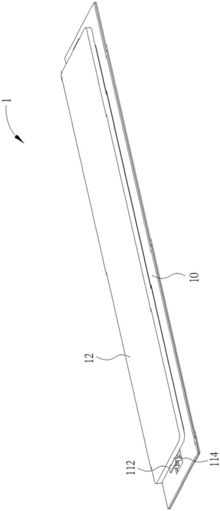
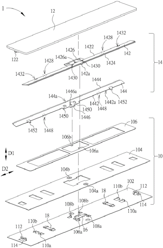
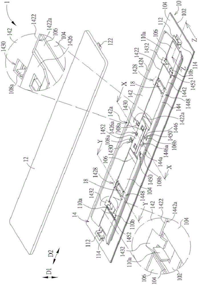
[0039] see Figure 1 to Figure 5 , figure 1 is a schematic diagram of a key structure 1 according to an embodiment of the present invention, figure 2 is the exploded diagram of button structure 1, image 3 is a partial exploded view of key structure 1, and its perspective is the same as figure 2 different, Figure 4 1 edge for the button structure image 3 Sectional view of midline X-X, Figure 5 1 edge for the button structure image 3 Sectional view of midline Y-Y. The key structure 1 includes a base 10 , a key cap 12 , a lifting mechanism 14 , a first magnetic member 16 and two second magnetic members 18 . The keycap 12 is arranged on the base 10, and the lifting mechanism 14 is arranged between the base 10 and the keycap 12, so that the keycap 12 can be opposite to the vertical direction (or the first direction, the same below) D1 through the lifting mechanism 14 Move up and down on the base 10 . The first magnetic member 16 and the second magnetic member 18 are...


PUM


Abstract

The invention relates to a key structure. The key structure comprises a base, a key cap, a lift mechanism and a magnetic element, wherein the key cap can vertically move relative to the base by the lift mechanism, the lift mechanism comprises a support, a magnetic part is arranged at one side edge part of the support, the side edge part is maintained to prop against the base by a sharp edge, the magnetic part outwards extends from the side edge part, the other opposite side edge part of the support is movably connected with the key cap, the magnetic element is arranged on the base in correspondence to the magnetic part, and a magnetic attractive force is generated between the magnetic element and the magnetic part; when the key cap is pressed by an external force, the support rotates relative to the base by the sharp edge, so that the magnetic part deviates from the magnetic element, and the key cap is close to the base; when the external force is released, the magnetic attractive force drives the support to rotate relative to the base by the sharp edge so as to make the key cap deviated from the base; and another magnetic element can be arranged on the base and can generate a magnetic attractive force on another magnetic part of the support, so that the side edge part is driven to prop against the base.

Description

[0001] This application is a divisional application for an invention patent application with an application date of August 29, 2014, an application number of 201410436255.2, and the invention name of "Key Structure". technical field [0002] The invention relates to a key structure, in particular to a mechanical key structure. Background technique [0003] The distance of up and down movement of traditional keys is relatively long, so it is easy to set a bowl-shaped rubber body under the keycap, so that when the keycap is pressed down, the bowl-shaped rubber body is also compressed downward to generate elastic force, and When the keycap is released, the elastic force generated by the rubber bowl drives the keycap up to return to its original position. However, with the trend of keyboard thinning, when the height of the keyboard's up and down movement is required to be reduced, the height of the bowl-shaped rubber body should also be reduced, but after the height of the bowl-...

Claims


Application Information

Patent Timeline
Patent Type & Authority Applications(China)
IPC IPC(8): H01H13/705
CPCH01H13/705H01H2215/042
Inventor 许建士
Owner DARFON ELECTRONICS (SUZHOU) CO LTD
Learn More