Connection structure of armature portion and pedestal of magnetic latching relay

A magnetic latching relay and connection structure technology, applied in the direction of electromagnetic relays, electromagnetic relay details, relays, etc., can solve problems affecting the stability of relay parameters, easy to generate assembly dross, product failure, etc., to improve product reliability, Small interference fit and less plastic lint

Active Publication Date: 2016-05-04
XIAMEN HONGFA ELECTRIC POWER CONTROLS
View PDF5 Cites 2 Cited by
  • Summary
  • Abstract
  • Description
  • Claims
  • Application Information

AI Technical Summary

Problems solved by technology

[0003] The matching structure between the armature part of the existing magnetic latching relay and the hole shaft of the base is generally designed as a simple round shaft with a round hole structure, that is, the armature part of the magnetic latching relay in the prior art is provided with a circular shaft, and the base is provided with a round hole , the axis of the round hole is set horizontally, and an opening is provided on the side wall of one side of the round hole. When the rotating shaft of the armature part is to be loaded into the round hole of the base, it is loaded from the opening. The existing armature part and the base The round shaft matching round hole scheme mainly has two structural features. One is the interference fit scheme, that is, the opening of the round hole of the base and the round shaft of the armature part are in an interference fit. In this way, the height of the opening must be Smaller than the height dimension between the upper and lower walls of the round hole, the height dimension between the upper and lower walls of the round hole is also the diameter of the round hole, and usually needs to have a certain amount of interference, this structural design, the round axis of the armature part After being installed into the round hole of the base, due to the large interference, it is not easy to come out, and the reliability is good. However, during the process of installing the round shaft of the armature part into the round hole of the base, it is easy to produce assembly dross, which affects The stability of the relay parameters; the other is the non-interference fit scheme, that is, the opening of the round hole of the base and the round axis of the armature part are non-interference fit, so that the height of the opening must be designed to be not less than the circle The height dimension between the upper and lower walls of the hole. With this structural design, no assembly debris will be generated during the process of installing the round shaft of the armature part into the round hole of the base. However, due to the large height dimension of the opening, the armature Part of the round shaft is easy to come out of the round hole of the base, resulting in product failure

Method used


Image

  • Connection structure of armature portion and pedestal of magnetic latching relay
  • Connection structure of armature portion and pedestal of magnetic latching relay
  • Connection structure of armature portion and pedestal of magnetic latching relay

Examples


Embodiment

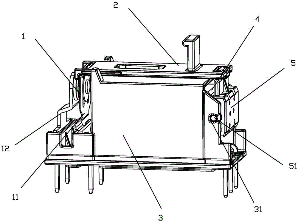
[0027] see Figure 1 to Figure 10 As shown, a magnetic latching relay of the present invention includes a magnetic circuit system, a contact system 1, a push part 2 and a base 3, wherein the magnetic circuit system is composed of a magnetic circuit part 4 and an armature part 5, and the contact system 1 includes a moving spring 11 and static spring 12; the pushing part 2 is a pushing block; the magnetic circuit part 4 usually includes a yoke, an iron core and a coil.

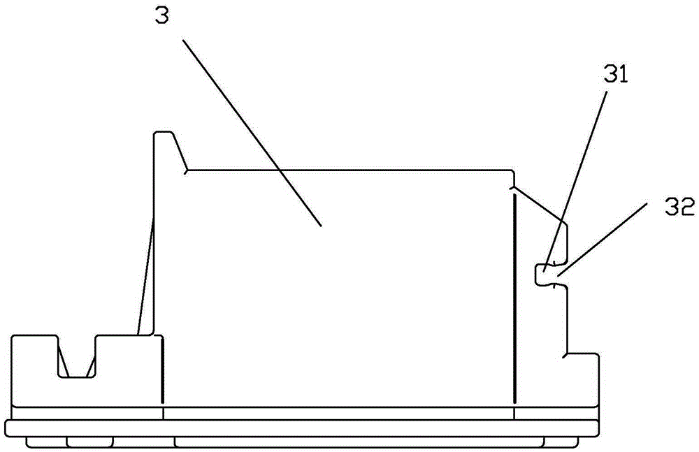
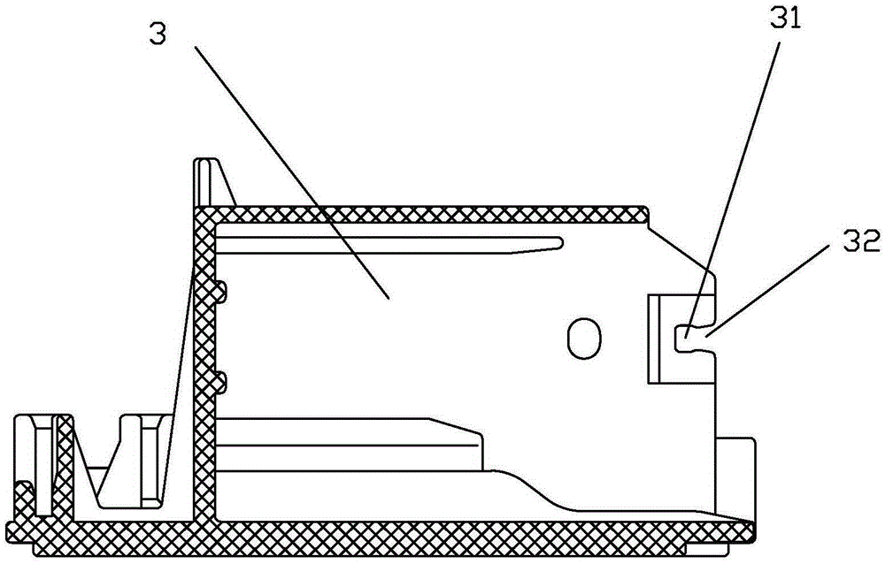
[0028] A connection structure between the armature part and the base of a magnetic latching relay in the present invention, the armature part 5 is provided with a circular rotating shaft 51, and the base 3 is provided with a shaft hole 31 for supporting the rotating shaft of the armature part. The rotating shaft 51 of the armature part 5 is fitted to rotate in the shaft hole 31 of the base. When the magnetic latching relay is reset or set, the rotating shaft 51 will rotate in the shaft hole in the forward or rev...


PUM


Abstract

The present invention discloses a connection structure of an armature portion and a pedestal of a magnetic latching relay. The connection structure comprises an armature portion and a pedestal; the armature portion is provided with a rotating shaft, and the pedestal is provided with a shaft hole, wherein the shaft hole is provided with an opening part; the height of the opening part is smaller than the height between the upper top wall and the lower bottom wall of the pedestal; and when the rotating shaft of the armature portion is disposed in the shaft hole of the pedestal along with the opening part, the rotating shaft is provided with an abdicating part at the height direction to allow the rotating shaft to be in microscale interference fit with the opening part after the abdicating part is reduced, and when the rotating shaft rotates to a resetting stabilization position or a setting stabilization position, the magnitude of interference of the rotating shaft is gradually increased up to the maximum between the height direction and the opening part, so that the rotating shaft is prevented from quitting from the shaft hole. According to the invention, it is ensured that the rotating shaft of the armature portion is not easy to take off after being installed into the hole of a pedestal, so that the reliability of products is improved, and plastic soft flocks generated in the process of installing the rotating shaft of the armature portion into the hole of the pedestal are small, so that the stability of relay parameters is ensured.

Description

technical field [0001] The invention relates to a magnetic latching relay, in particular to a connection structure between the armature part and the base of the magnetic latching relay. Background technique [0002] A magnetic latching relay usually includes a magnetic circuit system, a contact system, a push part and a base, wherein the magnetic circuit system generally consists of a magnetic circuit part and an armature part, and the two are usually fixed on the base or the coil frame. For the plastic round shaft armature structure, it is necessary to ensure the reliable fit of the relay during the action and avoid falling out, so the assembly process of the armature shaft and the base hole is usually an interference fit, and the greater the interference, the higher the assembly reliability, but The greater the interference, the greater the possibility of lint generated during the assembly process. Therefore, the design of the interference fit structure between the armatur...

Claims


Application Information

Patent Timeline
Patent Type & Authority Applications(China)
IPC IPC(8): H01H50/04H01H50/18
CPCH01H50/047H01H50/18
Inventor 齐宏亮钟叔明饶丽斌
Owner XIAMEN HONGFA ELECTRIC POWER CONTROLS
Why Eureka
Try Eureka