Array substrate, manufacturing method thereof and display device
A technology of an array substrate and a manufacturing method, which is applied in the display field, can solve the problems of easy occurrence of depression at the via hole, uneven diffusion of the alignment film, poor display panel, etc., so as to improve the display effect, achieve flattening, and solve the effect of poor Mura.
- Summary
- Abstract
- Description
- Claims
- Application Information
AI Technical Summary
Problems solved by technology
Method used
Image
Examples
Embodiment 1
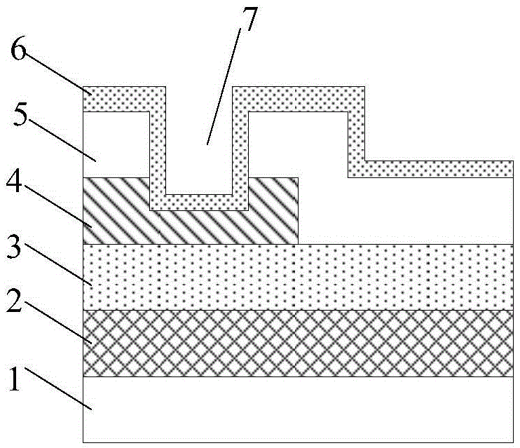
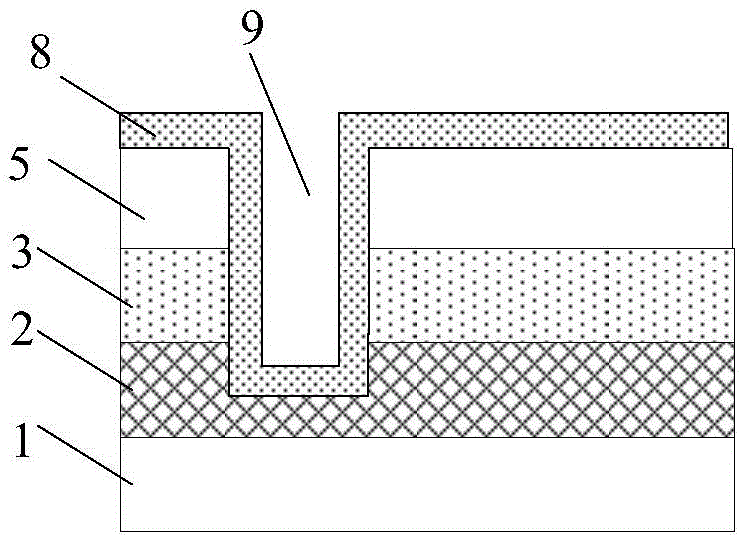
[0055] Such as figure 1 and figure 2 As shown, in the existing array substrate, in order to conduct the patterns located in different film layers, it is necessary to make via holes, the via holes include the pixel electrode via hole 7 connecting the pixel electrode 6 and the drain of the thin film transistor, and also include The common electrode via hole 9 connecting the common electrode 8 and the common electrode connection line is generally 7 μm*7 μm in size. These via holes are generally narrow and deep, so that depressions are prone to occur at the via holes, resulting in When the alignment film is coated on the upper surface, the alignment film is prone to uneven diffusion at the via holes, resulting in mura defects in the final display panel.
[0056] In order to solve the above problems, this embodiment provides an array substrate, including a first conductive pattern, an insulating layer covering the first conductive pattern, and a second conductive pattern on the i...
Embodiment 2
[0063] This embodiment provides a method for fabricating an array substrate, including forming a first conductive pattern, an insulating layer covering the first conductive pattern, and a second conductive pattern on the insulating layer, and the insulating layer includes Connecting the via holes of the first conductive pattern and the second conductive pattern, the method includes:
[0064]Before forming the second conductive pattern, forming a conductive column connected to the first conductive pattern in the via hole;
[0065] A second conductive pattern connected to the conductive column is formed.
[0066] In this embodiment, before forming the second conductive pattern on the insulating layer, a conductive column is made at the via hole in the insulating layer, and the conductive column is connected with the first conductive pattern under the insulating layer, so that the The first conductive pattern and the second conductive pattern are connected. Since the conductive ...
Embodiment 3
[0095] This embodiment provides a method for fabricating an array substrate, such as Figure 4 As shown, this embodiment includes the following steps:
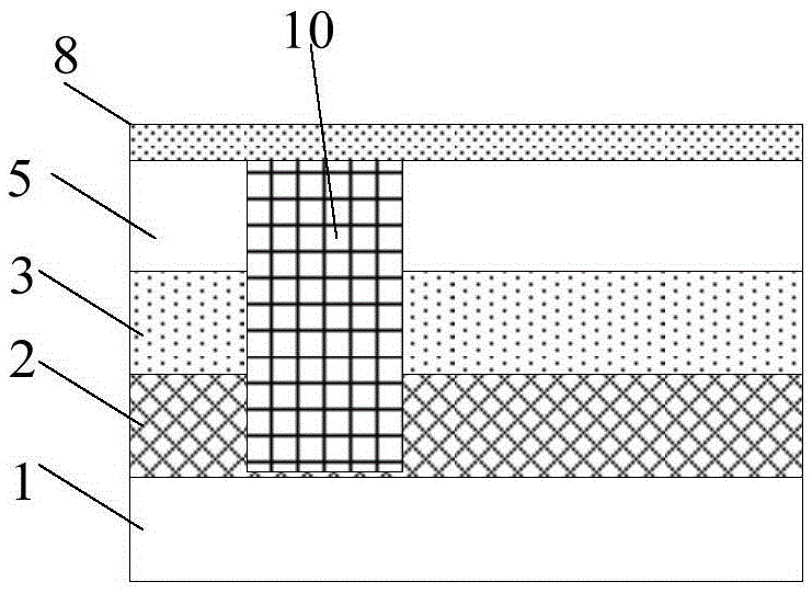
[0096] Step 31: Provide a base substrate 1, form conductive pillars 10 and gate lines, common electrode lines, and gates formed by the gate metal layer 2 on the base substrate 1, and connect the conductive pillars 10 to the common electrode lines;
[0097] Wherein, the base substrate 1 may be a glass substrate or a quartz substrate. The conductive column 10 can be made of the same material as the gate metal layer, so that the conductive column 10 can be formed simultaneously with the grid line, common electrode line, and gate through a patterning process; the conductive column 10 can also be made of an organic conductive polymer.
[0098] Alternatively, the main body of the conductive pillar 10 can be a resin pillar, and the resin pillar is wrapped with a conductive material. At this time, the conductive pillar 10, the gate l...
PUM
 Abstract
Description
Claims
Application Information
 - R&D
- Intellectual Property
- Life Sciences
- Materials
- Tech Scout
- Unparalleled Data Quality
- Higher Quality Content
- 60% Fewer Hallucinations
Browse by: Latest US Patents, China's latest patents, Technical Efficacy Thesaurus, Application Domain, Technology Topic, Popular Technical Reports.
© 2025 PatSnap. All rights reserved.Legal|Privacy policy|Modern Slavery Act Transparency Statement|Sitemap|About US| Contact US: help@patsnap.com


