
Multi-stage stator and rotor combined motor

A combined technology of stator and rotor, applied in the direction of electromechanical devices, electrical components, etc., can solve the problems of increasing weight and cost, reducing power density, complex structure, etc., and achieve high power density, high work efficiency, and high efficiency.

Active Publication Date: 2018-11-23
CHONGQING UNIV
View PDF22 Cites 0 Cited by
  • Summary
  • Abstract
  • Description
  • Claims
  • Application Information

AI Technical Summary

Problems solved by technology

However, in such a small space as the electric wheel of a car, the structure of the transmission will be very complicated to arrange and control, and it will inevitably increase the weight and cost, and reduce its power density

Method used


Image

  • Multi-stage stator and rotor combined motor
  • Multi-stage stator and rotor combined motor
  • Multi-stage stator and rotor combined motor

Examples


Embodiment Construction

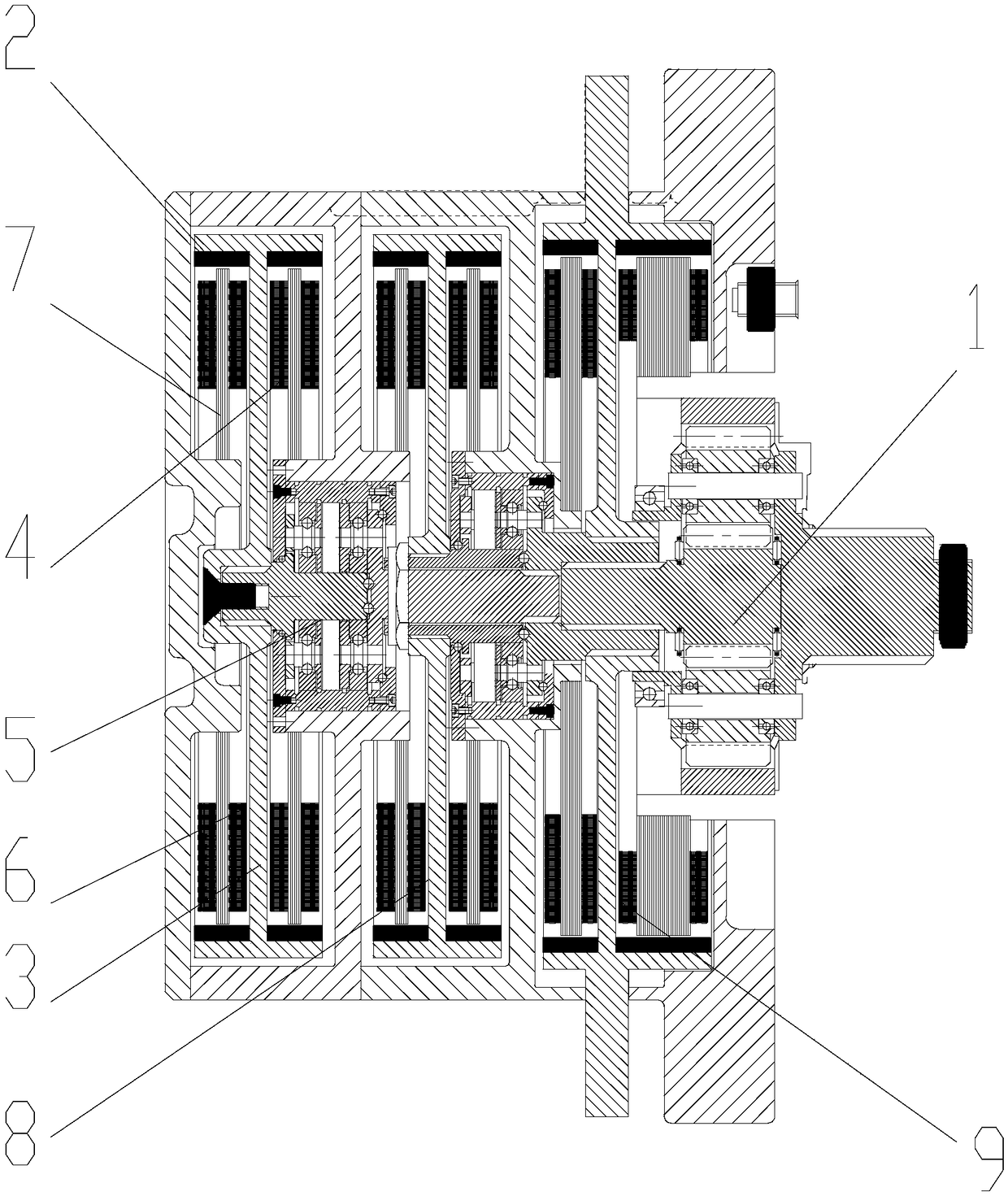
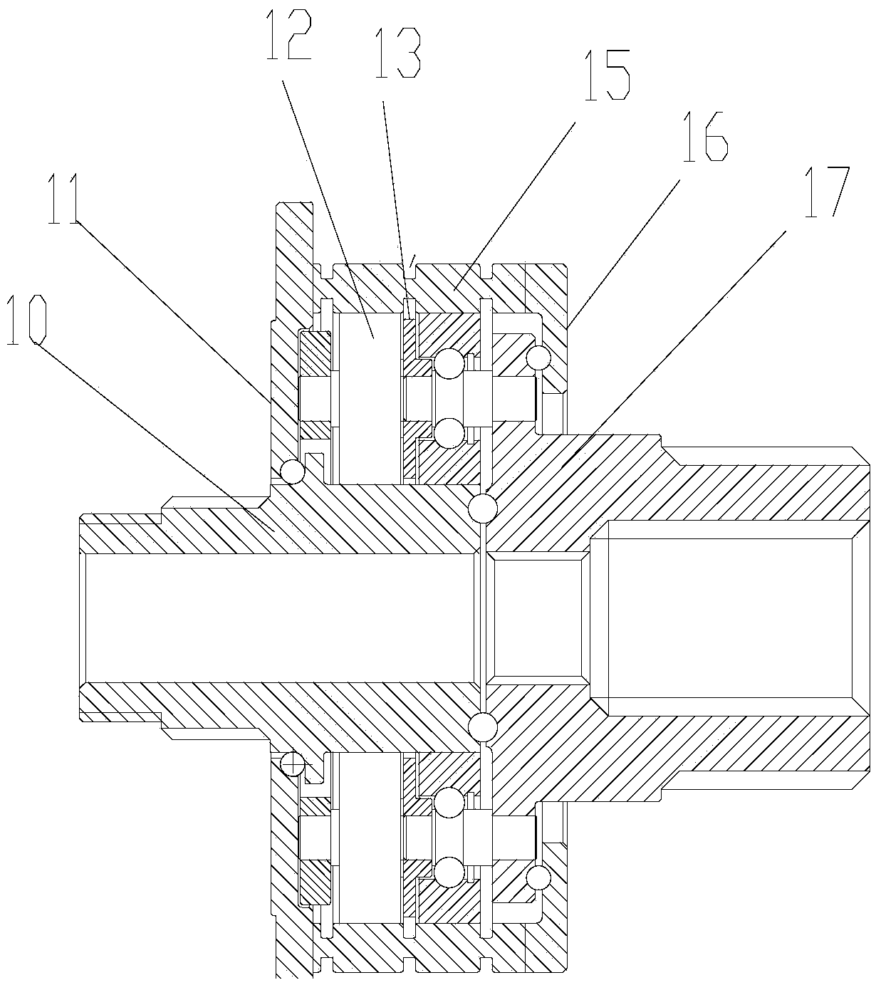
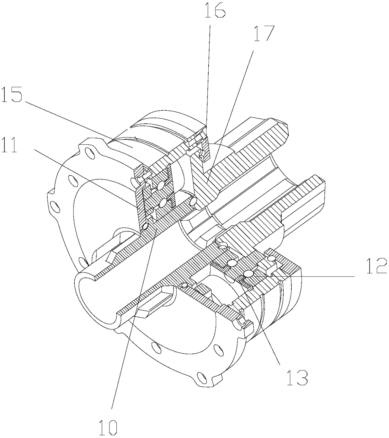
[0023] figure 1 It is a structural schematic diagram of the present invention; as shown in the figure, the multi-stage stator-rotor 3 combined motor of this embodiment includes at least two sub-motors with independent stators 7 and rotors 3, and at least one of the sub-motors is provided with a rotor 3 sub-reducers for power output; the output terminals of each sub-motor are connected and output power, and each stage of stator 7 and rotor 3 can output power and have an independent reduction ratio output. By setting the sub-motors of each level The transmission ratio of the reducer, through their working combination, can achieve wide torque and wide speed range and still maintain high working efficiency. It is suitable for low speed; the middle column motor has a moderate number of pole pairs and is equipped with a sub-reducer with moderate deceleration, and it will be suitable for medium speed; the right column motor has a small number of pole pairs and is equipped with a redu...


PUM


Abstract

The invention discloses a multi-stage stator / rotor combined motor, comprising at least two sub motors, wherein each sub motor is provided with a stator and a rotor which are independent from each other; at least one sub motor is provided with a sub speed reducer used for outputting the power of the corresponding rotor; the output ends of all the sub motors are in transmission connection and output power; each stage of sub motor of the motor can have an independent reduction ratio and through output matching, the motor can obtain relatively high working efficiency both in a large range of revolving speed and in a large range of torque; therefore, the motor is compact in structure and can realize relatively high power density.

Description

technical field [0001] The invention relates to the field of motors, in particular to a multi-stage stator-rotor combined motor. Background technique [0002] As we all know, rotary motors include a stator and a rotor, and the use of high-speed motors is one of the effective ways to increase the power density of the motor, because increasing the speed can increase the electromagnetic interaction range of the rotary motor stator and rotor per unit time. The output speed of the motor is often not so high. For example, the motor used for electric wheels of automobiles has a maximum wheel speed of about 1000 (rev / min). If a high-speed motor is used, a deceleration device needs to be added. Therefore, on the one hand, high-speed and low-torque is used to ensure the required power and realize small size and light weight; Combined and integrated in the motor. Due to the difference in the properties of the electromagnetic material of the motor and the mechanical properties of the ...

Claims


Application Information

Patent Timeline
Patent Type & Authority Patents(China)
IPC IPC(8): H02K16/00
CPCH02K16/00
Inventor 舒红宇季松杨彩霞
Owner CHONGQING UNIV
Learn More