
Signal generating system, signal generating method, and signal combining module

A technology of signal generation and signal combination, applied in the direction of pulse generation, electric pulse generation, multiple input and output pulse circuits, etc., can solve problems such as multiple noises

Inactive Publication Date: 2016-05-04
MEDIATEK INC
View PDF5 Cites 9 Cited by
  • Summary
  • Abstract
  • Description
  • Claims
  • Application Information

AI Technical Summary

Problems solved by technology

However, such adjustments may introduce more noise

Method used


Image

  • Signal generating system, signal generating method, and signal combining module
  • Signal generating system, signal generating method, and signal combining module
  • Signal generating system, signal generating method, and signal combining module

Examples


Embodiment Construction

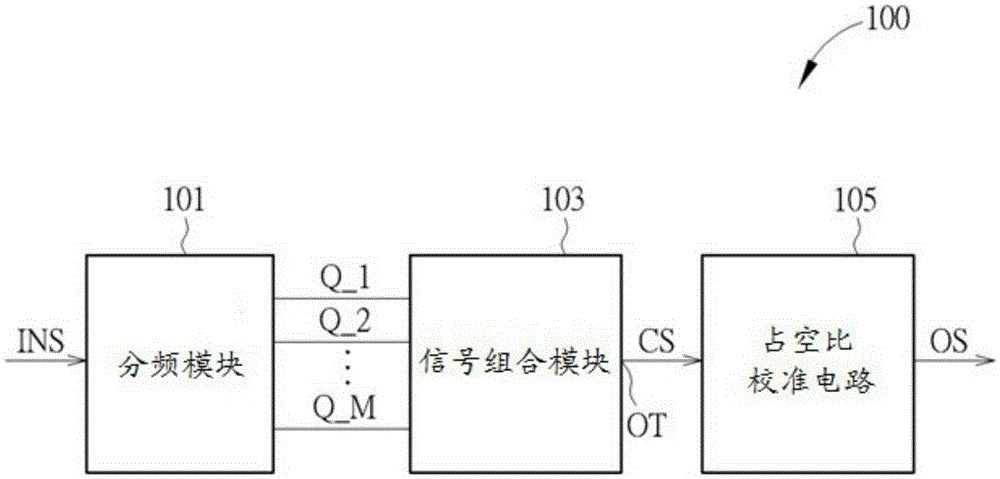
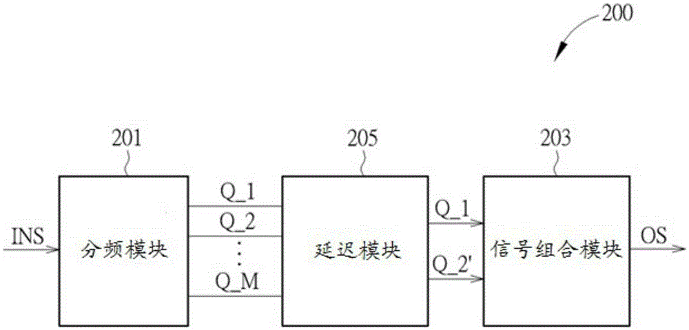
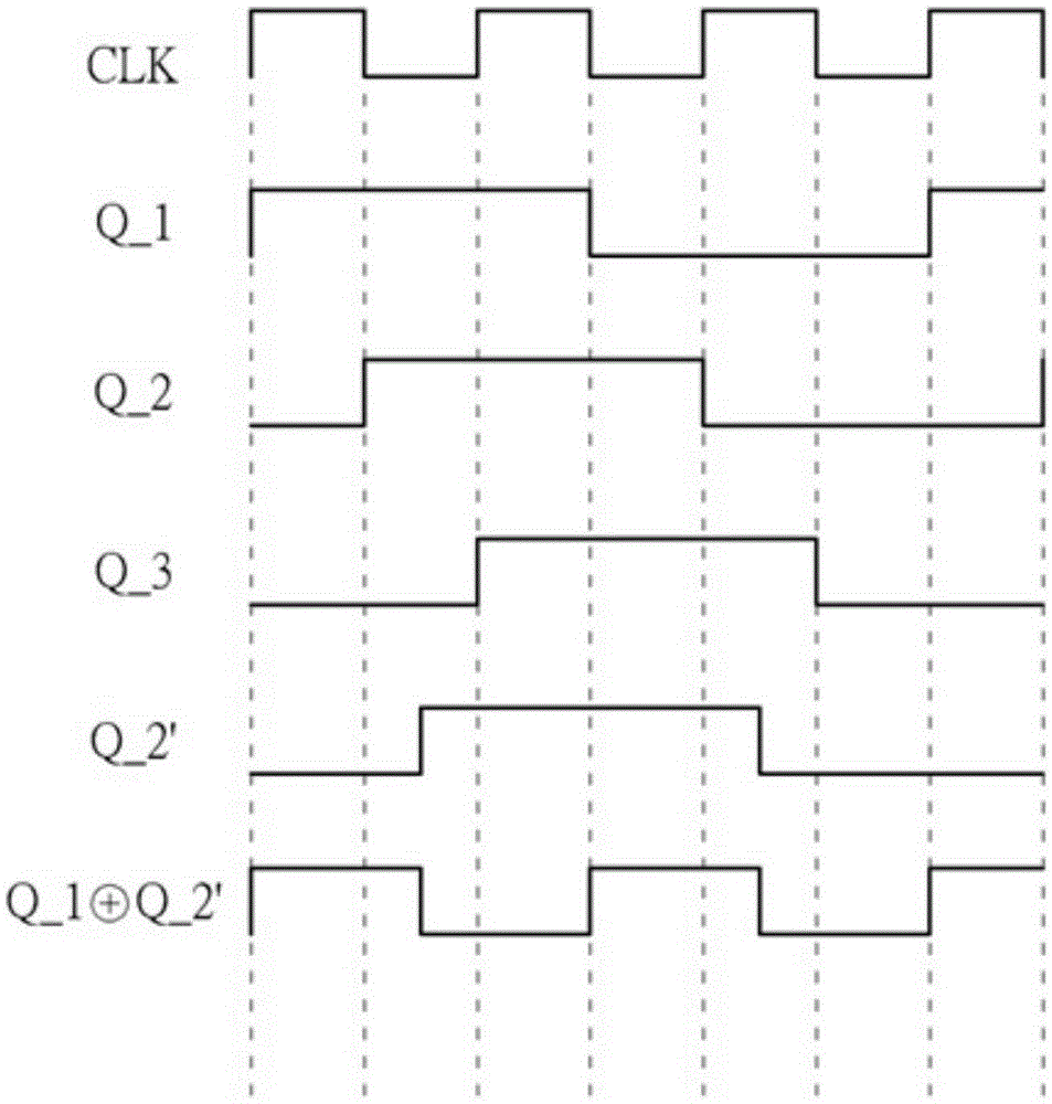
[0040] figure 1 It is a block diagram of a signal generating system 100 for generating an output signal OS with a duty cycle of 50% according to an embodiment of the present application. Such as figure 1As shown, the signal generation system 100 includes a frequency dividing module 101 and a signal combining module (signalcombiningmodule) 103 . The frequency division module 101 includes an odd number of level trigger devices, and uses a frequency division ratio equal to M to generate a plurality of frequency division signals Q_1-Q_M based on the input signal INS, wherein M is a positive integer. That is, M can be 1, or any other positive integer other than 1. The signal combining module 103 combines at least two of the frequency-divided signals Q_1 - Q_M to generate an output combined signal CS at the output terminal OT. In one embodiment, the frequency-divided signals Q_1-Q_M have a duty cycle of 50%, but their frequency is not the desired frequency. Alternatively, the si...


PUM


Abstract

A signal generating system for generating an output signal with a 50% duty cycle, comprising: a frequency dividing module, comprising an odd number of level triggering devices, for generating a plurality of frequency divided signals utilizing a frequency dividing ratio equaling to M, wherein the M is an positive integer; and a signal combining module, for combining at least two of the frequency divided signals to generate at least one output combined signal. The signal generating system generates the output signal based on the output combined signal. The frequency dividing module cooperates the signal combining module to provide a frequency dividing ratio equaling to N.5, wherein the N is a positive integer. According to the system, the output signals with quadrature phase and odd frequency-dividing ratio can be generated.

Description

【Technical field】 [0001] The invention relates to a signal generation system, a signal generation method and a signal combination module. 【Background technique】 [0002] Quadrature signals with accurate duty cycles are always necessary for circuits. For example, quadrature signals with accurate duty cycles facilitate oscillator coverage or frequency planning. [0003] Quadrature signals are commonly used, but conventional signal generation systems use only an even number of frequency dividers for quadrature signal generation. This is not conducive to oscillator coverage or frequency planning due to the limitation of the frequency division ratio. [0004] For example, if the signal generating system has 3 level triggering devices, the signal generating system can only generate frequency-divided signals with a phase of 180 / 3*N, where N is a positive integer. For another example, if the signal generating system has 5 level trigger devices, the signal generating system can on...

Claims


Application Information

Patent Timeline
Patent Type & Authority Applications(China)
IPC IPC(8): H03K3/283H03K5/26
CPCH03K3/283H03K5/26H03K5/1565H03K19/21H03K5/06
Inventor 曾聖哲王耀祺
Owner MEDIATEK INC
Learn More