
Urea solution jet control method of denitrification system based on dual MAPs

A MAP map, solution injection technology, applied in the controller, separation method, electric controller with specific characteristics, etc., can solve the problems of ammonia leakage, non-compliance with emission standards, low nitrogen oxide conversion rate, etc.

Active Publication Date: 2016-05-11
中国船舶集团有限公司第七一一研究所
View PDF6 Cites 4 Cited by
  • Summary
  • Abstract
  • Description
  • Claims
  • Application Information

AI Technical Summary

Problems solved by technology

If the injection volume is too small, the conversion rate of nitrogen oxides will be too low, which will not meet the emission standards, while if the injection volume is too large, the cost will be too high, and even ammonia gas will leak

Method used


Image

  • Urea solution jet control method of denitrification system based on dual MAPs
  • Urea solution jet control method of denitrification system based on dual MAPs
  • Urea solution jet control method of denitrification system based on dual MAPs

Examples


Embodiment Construction

[0016] The present invention will be described in detail below in conjunction with the accompanying drawings and specific embodiments.

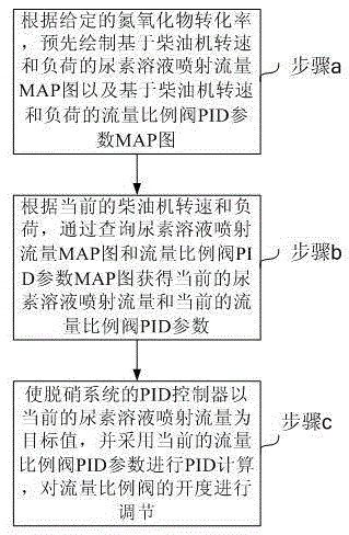
[0017] see image 3 . According to an embodiment of the present invention, a method for controlling urea solution injection in a denitrification system based on a double MAP diagram, wherein the denitrification system includes a flow proportional valve for controlling the injection flow rate of the urea solution, and the opening of the flow proportional valve is Controlled by a PID controller. The urea solution injection control method for the denitrification system based on the double MAP diagram comprises the following steps:

[0018] Step a, according to the given nitrogen oxide conversion rate, draw in advance the urea solution injection flow MAP diagram based on the diesel engine speed and load and the flow proportional valve PID parameter MAP diagram based on the diesel engine speed and load;

[0019] Step b, according to the current...


PUM


Abstract

The invention discloses a urea solution jet control method of a denitrification system based on dual MAPs. The urea solution jet control method comprises the following steps of drawing a urea solution jet flow MAP based on the rotating speed and the load of a diesel engine and a flow proportional valve PID (Proportion Integration Differentiation) parameter MAP based on the rotating speed and the load of the diesel engine in advance according to a given NOx conversion rate; obtaining current urea solution jet flow and current flow proportional valve PID parameters by inquiring the urea solution jet flow MAP and the flow proportional valve PID parameter MAP according to the rotating speed and the load of the diesel engine; carrying out PID calculation by a PID controller of the denitrification system by taking the current urea solution jet flow as a target value and adopting the current flow proportional valve PID parameters, and regulating the opening degree of a flow proportional valve. According to the urea solution jet control method disclosed by the invention, the urea solution jet flow of the denitrification system can be accurately controlled, so that the requirement on a preset NOx conversion rate is achieved, and the response speed is fast.

Description

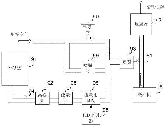
technical field [0001] The invention relates to a method for controlling injection of urea solution in a denitrification system. Background technique [0002] At present, selective catalytic reduction (SCR) is mainly used in the market to eliminate nitrogen oxides (NO x ), in order to reduce the emission of nitrogen oxides (NO x ) pollution to the environment. figure 1 A schematic diagram showing the structure of a denitration system for selective catalytic reduction (SCR). Such as figure 1 As shown, the urea solution in the storage tank 91 is pumped out by the centrifugal pump 92, and is delivered to the nozzle 93 after being mixed with the compressed air, and the nozzle 93 sprays the gas-liquid mixture of the urea solution and the compressed air into the discharge pipe 81 of the diesel engine 8 Inside. The nitrogen oxides in the diesel engine exhaust gas and the urea solution undergo a denitrification reaction in the reactor 7, and the reacted gas is discharged from t...

Claims


Application Information

Patent Timeline
Patent Type & Authority Applications(China)
IPC IPC(8): B01D53/94B01D53/56G05B11/42
CPCB01D53/56B01D53/9409B01D2258/012B01D2259/124G05B11/42
Inventor 李文荣钱泽群兰锋张呈龙王剑平石浩舰
Owner 中国船舶集团有限公司第七一一研究所
Learn More