Mechanical hand device

A technology of manipulators and manipulators, applied in the direction of manipulators, chucks, manufacturing tools, etc., can solve the problems of broken ropes, swing angles, and inability to accurately grasp objects, etc., and achieve the effect of enhancing the force value of the ropes

Active Publication Date: 2016-05-11
ZHUHAI PANSHI ELECTRONICS TECH CO LTD
View PDF10 Cites 14 Cited by
  • Summary
  • Abstract
  • Description
  • Claims
  • Application Information

AI Technical Summary

Problems solved by technology

[0007] In the prior art, the manipulator is usually directly installed on the aircraft. When the manipulator grasps the object, it cannot be accurately grasped by the influence of the airflow of the airc...

Method used


Image

  • Mechanical hand device
  • Mechanical hand device
  • Mechanical hand device

Examples


Embodiment 1

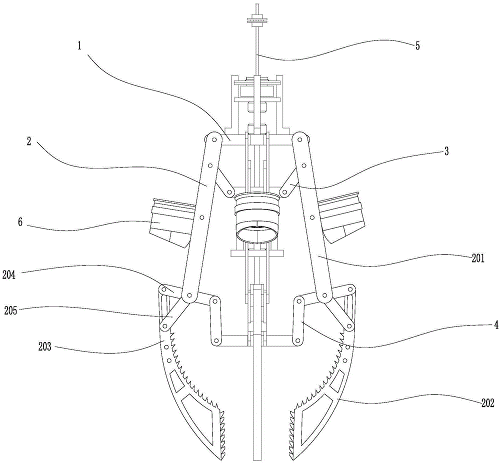
[0044] Such as figure 1 As shown, the manipulator device of this embodiment includes: a frame 1 , at least one pair (for example, two pairs) of grasping mechanisms 2 that open and close synchronously, a first control mechanism 3 , a second control mechanism 4 , and a suspension mechanism 5 .

[0045] There are two pairs of four grabbing mechanisms, and the distance between adjacent grabbing mechanisms is 90°. Two grabbing mechanisms in every pair of grabbing mechanisms are arranged symmetrically; each grabbing mechanism includes a mechanical arm 201 positioned above and a mechanical claw 202 positioned below, the upper end of the mechanical arm 201 is hinged on the frame 1, and the mechanical claw 202 Connected to the lower end of the mechanical arm 201; the mechanical arm is provided with a rotor unit 6. The mechanical claw 202 includes a claw body 203, a cross bar 204, and a slanting bar 205, and the claw body 203, the cross bar 204, and the slanting bar 205 are hinged to f...

Embodiment 2

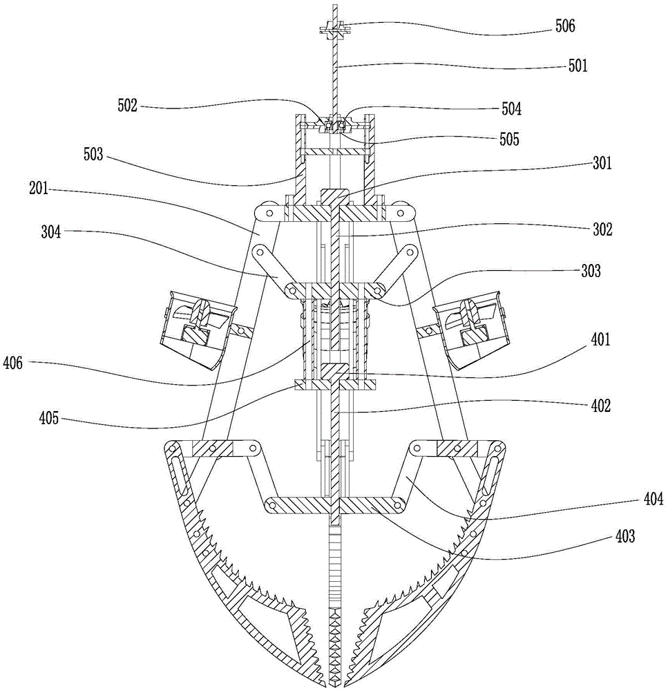
[0051] Such as Figure 6 As shown, the difference between this embodiment and embodiment 1 is:

[0052] 1. Suspension mechanism 6 includes a buffer 601, an upper connector 602, a lower connector 603, and an upper support plate; the upper support plate is located above the frame, and is fixedly connected with the frame through an upper fixing column; the middle part of the upper support plate is fixed with For the bearing, the lower connecting piece passes through the central hole of the bearing, and a limit block is connected to the bottom of the lower connecting piece, and the limit block is located below the bearing. Buffer 601 is located between upper connector 602 and lower connector 603; the upper connector is a flexible connector (such as a rope); the lower connector 603 is a rigid connector (such as a steel bar), and the lower connector 603 includes a vertical The straight section 604 and the bent section 605 above, and the vertical section 604 and the bent section 605...

Embodiment 3

[0055] The difference between this embodiment and Embodiment 1 is that: a pressure sensor is provided on the grabbing mechanism to detect the pressure used when grabbing objects; a camera and a distance sensor are installed at the bottom of the center of the manipulator device to facilitate grabbing objects .


PUM


Abstract

The invention provides a mechanical hand device which comprises a rack and at least a pair of grabbing mechanisms synchronously opened and closed, wherein two grabbing mechanisms in each pair are symmetrically arranged; each grabbing mechanism comprises a mechanical arm located at the upper side and a mechanical claw located at the lower side, the upper end of the mechanical arm is articulated on the rack, and the mechanical claw is connected with the lower end of the mechanical arm; and a ducted fan is arranged on the mechanical arm. Through arrangement of the two control mechanisms, the maximum value of the diameter of an article grabbed by a traditional standard mechanical hand is changed, and the mechanical hand device can flexibly grab articles; as the ducted fan is arranged, when the article is grabbed, the mechanical hand device can move horizontally for directed grabbing under the control of the ducted fan, so as to avoid the awkward situation that the article can not be grabbed due to natural factors or other factors; an upper supporting plate is used for fixing a bearing, and a rope is fixed on the bearing, so that the rope can not be fractured due to rotation although the mechanical hand spins in the air; and a buffering piece is also arranged on the rope, thereby enhancing the stressed value of the rope.

Description

technical field [0001] The invention relates to a manipulator device. Background technique [0002] The manipulator can imitate certain movement functions of the human hand and arm to grab, carry objects or operate tools according to a fixed program. The manipulator is the earliest industrial robot and the earliest modern robot. The research on manipulators began in the middle of the 20th century. From the United States United Control Corporation developed the first manipulator in 1958, the manufacturing industry began to introduce the use of manipulators in the early 1970s, and then to the development of my country's first manipulator in 1972 and the subsequent development of manipulators. Since then, manipulators have been developed and applied all over the country. The development of manipulators has gone through just a few decades, and a new look of the manufacturing industry is ushered in. Industrial manipulators have been widely used due to their own significant advant...

Claims


Application Information

Patent Timeline
IPC IPC(8): B25J15/10B25J19/00B25J19/02B25J19/04
CPCB25J15/10B25J19/00B25J19/02B25J19/04
Inventor 何春旺
Owner ZHUHAI PANSHI ELECTRONICS TECH CO LTD
Why Eureka
Try Eureka