Plastic injection mold for plastic gear

A technology for injection moulds and plastic gears, applied in the field of injection moulds, can solve the problems of affecting the service life of gears, hollowing out, affecting the image of enterprise products, etc., and achieve the effect of speeding up the setting work, simple structure and reducing hollowing phenomenon.

Inactive Publication Date: 2016-05-11
重庆和佳机械部件制造有限公司
View PDF0 Cites 0 Cited by
  • Summary
  • Abstract
  • Description
  • Claims
  • Application Information

AI Technical Summary

Problems solved by technology

At present, the commonly used production method of plastic gears is to use injection molds for injection molding. The production speed is fast and the qualified products are very high. However, the current gear injection molds are affected by the ambient temperature during the production of injection molding, and the produced gears sometimes appear hollow in the middle. Phenomenon, which affects the service life of the gear, and affects the image of the company's products

Method used


Image

  • Plastic injection mold for plastic gear
  • Plastic injection mold for plastic gear

Examples


Embodiment 1

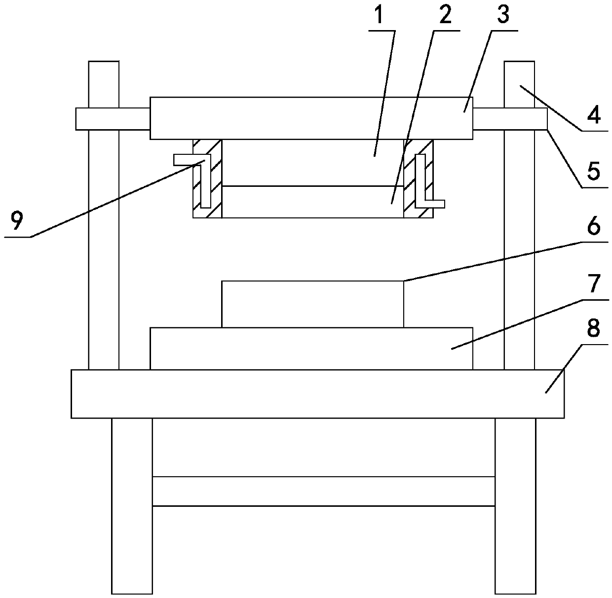
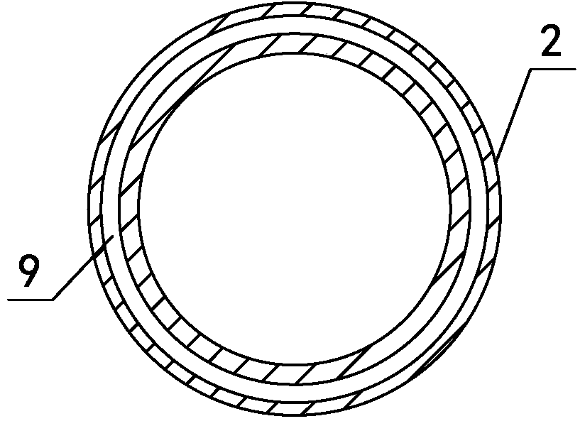
[0015] Such as figure 1 , figure 2 As shown, the injection mold for plastic gears, the injection mold for plastic gears, includes a workbench 8, an injection upper mold 1 and an injection lower mold 6 that cooperate with each other, and the injection lower mold 6 is installed on the lower template 7, and the lower template 7 Installed on the workbench 8, the top of the injection molding upper mold 1 is installed on the upper template 3, and guide pillars 4 are vertically arranged on the workbench 8 on the left and right sides of the lower template 7, and guide sleeves 5 are set on the guide pillars 4, The guide sleeves 5 are correspondingly fixed on the upper template 3, and the outer periphery of the upper mold 1 is covered with a thermal insulation cover 2. The thermal insulation cover 2 is made of aluminum alloy material, and a cooling cavity 9 is opened in the wall of the thermal insulation cover 2. The cooling cavity 9 The cross section of the insulation cover 2 is a ri...

Embodiment 2

[0019] Further changes are made on the basis of the first embodiment, the wall thickness of the thermal insulation cover 2 is 55 mm; the distance between the cooling chamber 9 and the side wall of the thermal insulation cover 2 is changed to 15 mm. Others are the same as embodiment one.

Embodiment 3

[0021] Further changes are made on the basis of the first embodiment, the wall thickness of the thermal insulation cover 2 is 60mm; the distance between the cooling cavity 9 and the side wall of the thermal insulation cover 2 is changed to 20mm. Others are the same as embodiment one.


PUM


Abstract

The invention relates to a plastic injection mold for a plastic gear and belongs to the technical field of plastic injection molds. The plastic injection mold comprises a worktable, as well as an upper plastic injection mold and a lower plastic injection mold which are mutually matched, wherein the lower plastic injection mold is mounted on a lower template; the lower template is mounted on the worktable; the top of the upper plastic injection mold is mounted on an upper template; a guide pillar is vertically arranged at each of the left side and the right side of the lower template and mounted on the worktable; a guide sleeve sleeves each guide pillar; the guide sleeves are correspondingly fixed on the upper template; an insulated sleeve made of an aluminum alloy material sleeves the periphery of the upper plastic injection mold; a cooling cavity is formed in the wall of the insulated sleeve. The plastic injection mold is simple in structure; when the plastic injection mold is used for plastic injection of the gear, under the action of the insulated sleeve, a certain heat preservation function can be performed on the plastic injection environment, so that the hollow probability of the gear produced by plastic injection molding is reduced, and the product qualification rate is improved.

Description

technical field [0001] The invention relates to an injection mold for plastic gears, belonging to the technical field of injection molds. Background technique [0002] Gear transmission is a common transmission mode in people's life, and its transmission stability is very high, and its service life is long. With the continuous advancement of science and technology, more and more gears are made of plastic, which are mainly used in an industry with a small transmission torque. The production cost is low, the transportation cost is low, and the safety and maintenance are also convenient. At present, the commonly used production method of plastic gears is to use injection molds for injection molding. The production speed is fast and the qualified products are very high. However, the current gear injection molds are affected by the ambient temperature during the production of injection molding, and the produced gears sometimes appear hollow in the middle. Phenomenon, which affec...

Claims


Application Information

Patent Timeline
IPC IPC(8): B29C45/26B29C45/73
Inventor 胡维秀
Owner 重庆和佳机械部件制造有限公司
Why Eureka
Try Eureka