Automatic safe take-up wheel

A take-up wheel, a safe technology, applied in the field of electric power, can solve problems such as taking a long time and not pulling the wire smoothly

Active Publication Date: 2016-05-11
广州市兆能有限公司
View PDF8 Cites 4 Cited by
  • Summary
  • Abstract
  • Description
  • Claims
  • Application Information

AI Technical Summary

Problems solved by technology

[0003] Aiming at the problems caused by temporary laying of cables during the construction process, such as unsmooth pulling and taking a long time, the present invention provides an automatic safety take-up wheel, the purpose of which is to lay the cables as soon as possible and take them up in a short time as soon as possible. And it will not affect the next use

Method used


Image

  • Automatic safe take-up wheel
  • Automatic safe take-up wheel
  • Automatic safe take-up wheel

Examples


Embodiment 1

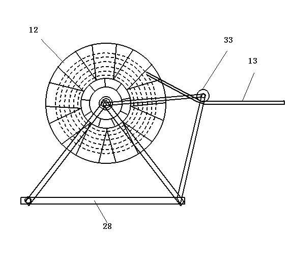
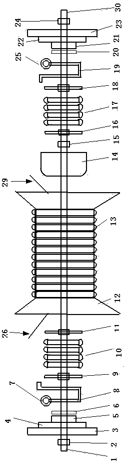
[0016] figure 2 It is an exploded view of the structure in the rotating shaft of the present invention. In the figure, the left and right parts of the wire wheel 12 are actually assembled on the central shaft 1 or 30 inside the center sleeve of the wire wheel 12. The fixed barrel 14 is located in the middle of the wire wheel, and the right end of the fixed barrel 14 is provided with a limit bolt 15. The left and right parts of other components are arranged symmetrically. The following is a summary between the left and right parts of each component. The number is the part on the left, and the number behind it is the part on the right. What middle position is provided with is barrel 14, is provided with spring in barrel 14, plays the dynamic effect of automatic winding cable, and one end of spring is fixedly connected on the central shaft, and the other end is fixed together with wire wheel 12, Close to the two ends of the barrel and the limit screw, there are symmetrically ar...

Embodiment 2

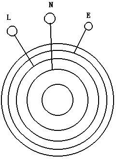
[0021] image 3 is a schematic diagram of a contact ring on one side of a multiphase cable. Ring-shaped point contact wires are arranged on the contact ring (6 or 20), respectively connected to the three-phase lines N, L, and E of the cable.

[0022] Figure 4 It is a schematic diagram of the contact between the three-phase U-shaped copper strip and the contact ring. When the three-phase line is connected to the three U-shaped copper strips set on one side, three mutually insulated concentric contacts need to be set. In this embodiment They are three copper strips: copper strip one 8a or 19a, copper strip two 8b or 19b, copper strip three 8c or 19c, and the copper strips are separated by insulating spacers 32 to prevent short circuits between the three-phase circuits. The contact terminals are set on the three U-shaped copper strips, and under the action of the compression spring, they are respectively connected with the ring-shaped point contact wires on the contact ring (6...


PUM


Abstract

The invention relates to an automatic safe take-up wheel, and belongs to the field of electric power. Screw threads are arranged on a center shaft; a wire wheel is arranged on the center shaft; the center shaft is arranged in a center sleeve of the wire wheel; a clockwork spring box is arranged in the middle position of the center shaft; one end of a clockwork spring is connected with the center shaft; the other end of the clockwork spring is connected onto the wire wheel; a cable is wound on the wire wheel; a conducting component is also arranged on the center shaft; the inner layer cable end is connected onto the conducting component from the wire wheel side; and wiring terminals are arranged on the conducting component. By using the technical scheme, unidirectional electric power can be connected, and three-phase electric power can also be connected; meanwhile, the automatic rotation of the wire wheel for cable winding can be realized; the automatic cable take-up and pay-off can be realized; and great convenience is brought to constructors.

Description

technical field [0001] The invention relates to a take-up reel, in particular to an automatic safety take-up reel, which belongs to the field of electric power. Background technique [0002] In the project construction, some temporary wires are often needed, and the cables covered with soft rubber are usually used. However, once these cables have a certain distance, the cables are often used without clues, like a pair of messy wires. It is very troublesome to use. It takes a long time just to comb the cables, which seriously affects the work efficiency. After the cables are used, they need to be retracted. It also takes quite a long time. It is neatly coiled up, but the time until the next use of the cable is not certain, and it needs to be moved constantly in the middle, especially for some temporary construction sites, there is no formal warehouse, let alone shelf placement, after many times of moving A moving cable will destroy the original coiling sequence, and it will ...

Claims


Application Information

Patent Timeline
Patent Type & Authority Applications(China)
IPC IPC(8): B65H75/38B65H75/48B65H75/44
CPCB65H75/38B65H75/4481B65H75/486B65H2701/34
Inventor 袁国堂
Owner 广州市兆能有限公司
Why Eureka
Try Eureka