Guide vane component, centrifugal compressor and air conditioner

A technology of centrifugal compressors and components, applied in the field of compressors, which can solve the problems of inability to fully guarantee the synchronization position of guide vanes, loss, inconsistent airflow, etc.

Inactive Publication Date: 2015-04-29
GREE ELECTRIC APPLIANCES INC +1
View PDF6 Cites 9 Cited by
  • Summary
  • Abstract
  • Description
  • Claims
  • Application Information

AI Technical Summary

Problems solved by technology

[0002] In order to expand the operating range of the centrifuge, inlet guide vanes are usually added at the inlet of the compressor to adjust the suction and discharge capacity of the entire centrifuge. However, if the angles of the guide vanes are not synchronized, the airflow between the blades will be inconsistent. When the blades are mixed, there will be losses, which will affect the performance of the whole unit
[0003] At present, there are two commonly used driving methods for the guide vane in the adjustment mechanism of centrifugal compressors. The first structure is to assemble the vane and the connecting rod through a key connection, and the drive shaft of the external stepping motor drives the active connecting rod. joint to make the drive ring rotate, and then the drive ring drives the driven connecting rod and the guide vane to rotate synchronously through the spherical coupling. The guide vane is in the synchronous position; the second structure is to assemble the vane and the pulley together through a key connection, drive the driving pulley through an external stepping motor, and the driving pulley drives other driven pulleys through a wire rope, and then the pulley drives the guide vane to synchronize Rotation, the structure is very prone to failure due to slippage between the steel wire rope and the bearing

Method used


Image

  • Guide vane component, centrifugal compressor and air conditioner
  • Guide vane component, centrifugal compressor and air conditioner
  • Guide vane component, centrifugal compressor and air conditioner

Examples


Embodiment Construction

[0024] The present invention will be described in further detail below in conjunction with the accompanying drawings and specific embodiments, but not as a limitation of the present invention.

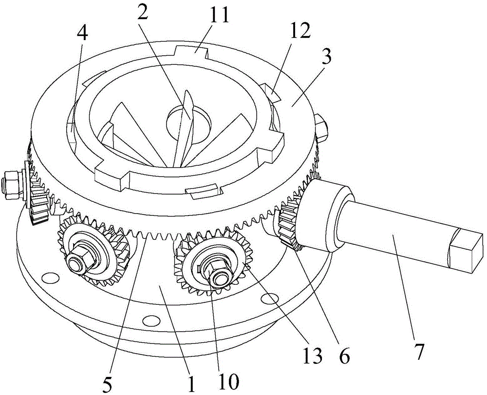
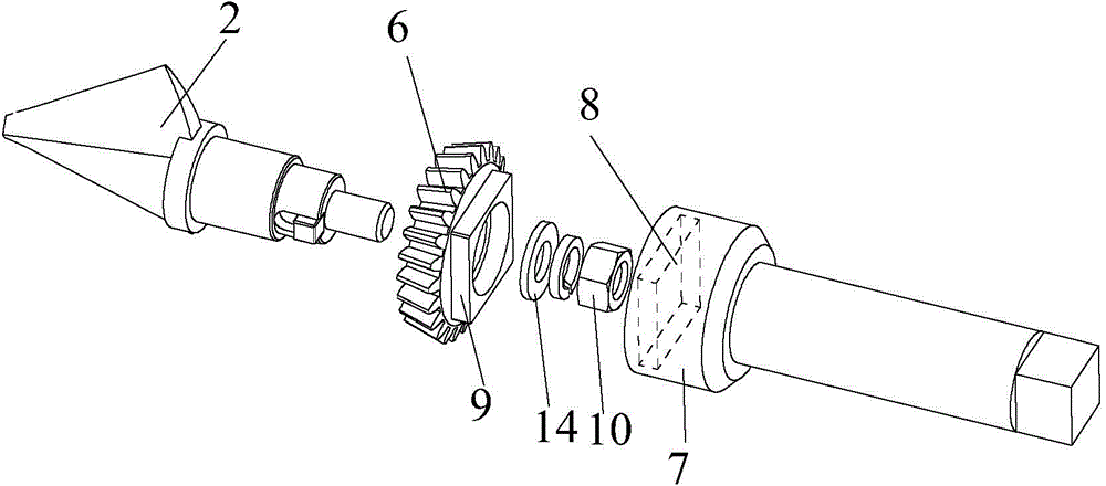
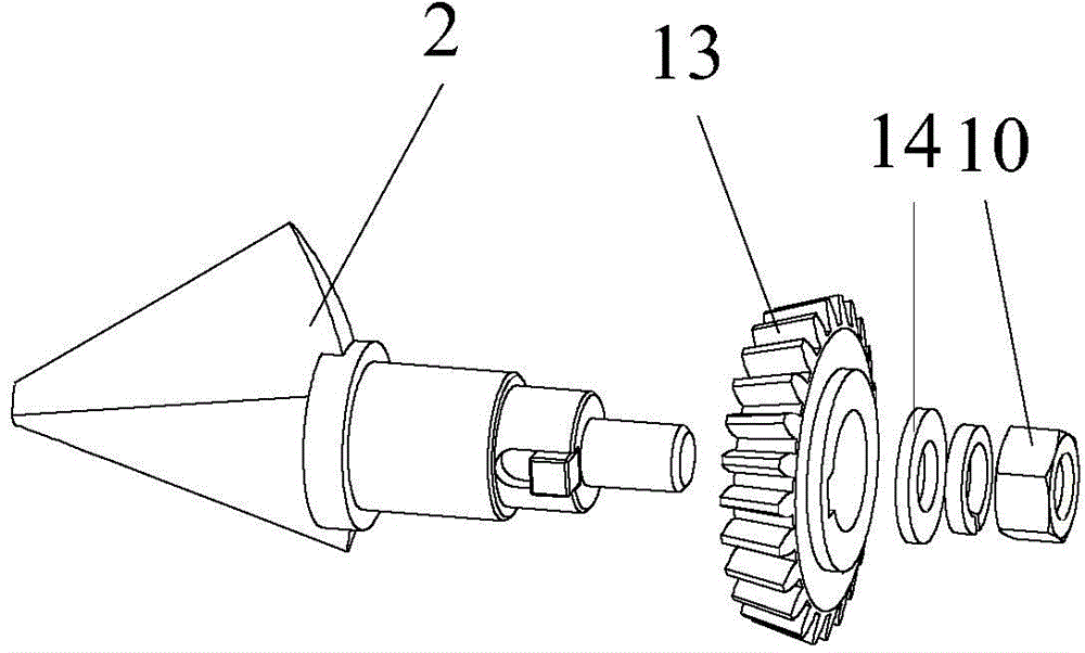
[0025] see Figure 1 to Figure 4 As shown, according to the embodiment of the present invention, the guide vane assembly includes a deflector 1 , a guide vane 2 , a driving ring 3 and a driving mechanism, and the guide vane 2 and the driving ring 3 are installed on the deflector 1 . The guide vane 2 is arranged along the radial direction of the flow deflector 1 and installed in the middle of the flow deflector 1 . The guide vane 2 includes a blade end located inside the deflector 1 and a blade tail end located outside the deflector 1 . A plurality of guide vanes 2 are evenly arranged along the circumferential direction of the deflector 1, and the blade tail end of each guide vane 2 is provided with a first gear, and the first gear is fixedly connected with the guide vanes 2 to form a ...


PUM


Abstract

The invention discloses a guide vane component, a centrifugal compressor and an air conditioner. The guide vane component comprises a flow guider (1), guide vanes (2), a driving ring (3) and a driving mechanism, wherein the guide vanes (2) are distributed along the circumference of the flow guider (1); first gears are arranged at vane tail ends of the guide vanes (2); the driving ring (3) sleeves the flow guider (1); a second gear (5) meshed with the first gears of the guide vanes (2) is arranged on one side, facing to the guide vanes (2), of the driving ring (3); the driving mechanism is in driving connection with the driving ring (3), so as to drive the driving ring (3) to rotate. According to the guide vane component provided by the invention, control precision is high and stabilizing performance is excellent.

Description

technical field [0001] The invention relates to the technical field of compressors, in particular to a guide vane assembly, a centrifugal compressor and an air conditioner. Background technique [0002] In order to expand the operating range of the centrifuge, inlet guide vanes are usually added at the inlet of the compressor to adjust the suction and discharge capacity of the entire centrifuge. However, if the angles of the guide vanes are not synchronized, the airflow between the blades will be inconsistent. When the blades are mixed, there will be losses, which will affect the performance of the whole unit. [0003] At present, there are two commonly used driving methods for the guide vane in the adjustment mechanism of centrifugal compressors. The first structure is to assemble the vane and the connecting rod through a key connection, and the drive shaft of the external stepping motor drives the active connecting rod. joint to make the drive ring rotate, and then the dr...

Claims


Application Information

Patent Timeline
Patent Type & Authority Applications(China)
IPC IPC(8): F04D29/46
CPCF04D29/462
Inventor 蒋楠张治平钟瑞兴蒋彩云谢蓉刘建飞陈玉辉黄保乾张竞周义
Owner GREE ELECTRIC APPLIANCES INC
Why Eureka
Try Eureka