Roller type drying and sintering or roasting device

A roasting device and drum-type technology, applied in drying, drying machine, drying gas arrangement, etc., can solve the problems of large flue gas consumption, huge equipment, high discharge temperature, etc., and achieve the effect of wide application range

Inactive Publication Date: 2017-05-17
唐竹胜
View PDF0 Cites 7 Cited by
  • Summary
  • Abstract
  • Description
  • Claims
  • Application Information

AI Technical Summary

Problems solved by technology

[0006] Vertical flash or boiling dryers can only dry powdery materials, but the equipment is huge, the consumption of flue gas is large, the discharge volume is also large, the discharge temperature is also high, the energy consumption is high, and the failure rate of the device is high

Method used


Image

  • Roller type drying and sintering or roasting device
  • Roller type drying and sintering or roasting device
  • Roller type drying and sintering or roasting device

Examples


Embodiment 1

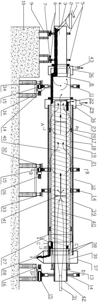
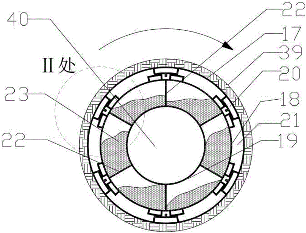
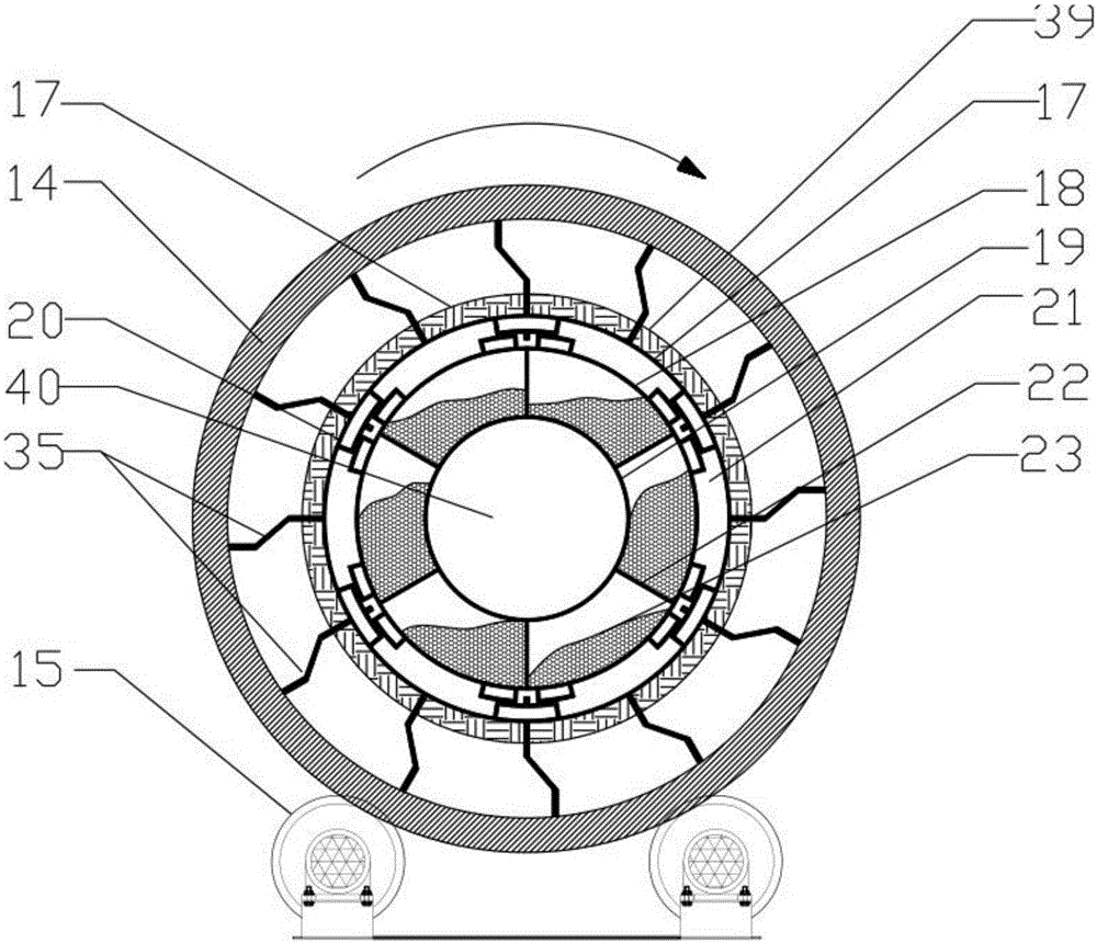
[0056] Such as Figure 1-8 As shown, a drum drying, sintering or roasting device includes a kiln body, a feeding device and a driving device. The kiln body is in the shape of a hollow cylinder. The preheating section 11, the drying drum 12 in the middle and the high temperature section 13 at the end of the kiln. The driving device includes a supporting roller mechanism 15, a driving motor 16 and a supporting column 9. The supporting roller mechanism includes a kiln head supporting roller mechanism, a roller supporting roller mechanism and a kiln The tail supporting wheel mechanism, the kiln head supporting wheel mechanism, the drum supporting wheel mechanism and the kiln tail supporting wheel mechanism are respectively located under the kiln head preheating section, the drying drum and the kiln tail high temperature section of the kiln body. The kiln head supporting wheel mechanism, The roller supporting wheel mechanism and the kiln tail supporting wheel mechanism are respecti...

Embodiment 2

[0060] Such as Figure 1-8 As shown, a drum drying, sintering or roasting device includes a kiln body, a feeding device and a driving device. The kiln body is in the shape of a hollow cylinder. Preheating section 11, drying drum 12 and kiln tail high temperature section 13, the driving device includes supporting ring 14, supporting wheel mechanism 15, driving motor 16 and supporting column 9, supporting ring includes kiln head supporting ring, drum supporting ring and kiln tail The support ring and the supporting wheel mechanism include the kiln head supporting wheel mechanism, the roller supporting wheel mechanism and the kiln tail supporting wheel mechanism. The kiln head supporting ring, the roller supporting ring and the kiln tail supporting ring are respectively located in the kiln head preheating section On the outside of the dry drum and the high-temperature section at the kiln tail, the size of the kiln head support ring, drum support ring and kiln tail support ring ar...


PUM


Abstract

The invention relates to a roller type drying and sintering or roasting device which comprises a kiln body and a drive device. A drying roller comprises a kiln body outer shell, a net-shaped outer sleeve and a net-shaped inner sleeve from outside to inside in the radial direction of the drying roller. The inner wall of the kiln body outer shell and the outer wall of the net-shaped outer sleeve are connected through a plurality of sliding drive shifting blocks evenly distributed in the circumferential direction, and rotary drive is carried out. A powder chamber is formed by a space between the kiln body outer shell and the net-shaped outer sleeve. The net-shaped outer sleeve and the net-shaped inner sleeve are connected through a plurality of net-shaped partitions spirally extending in the length direction of the kiln body. A space between the net-shaped outer sleeve and the net-shaped inner sleeve is divided by the partitions into a plurality of drying or roasting (sintering) material chambers distributed in the circumferential direction. An inner sleeve air chamber is formed by a space in the inner sleeve. The device has the beneficial effects that material drying is even, thorough and fast; the manmade pellet (spherical block) damage rate is low; the device investment is reduced; the productivity is greatly improved; and energy saving and emission reduction are realized.

Description

technical field [0001] The invention relates to a drying device, in particular to a drum-type device capable of drying, sintering or roasting. Background technique [0002] The existing drying equipment on the market mainly includes tower (shaft furnace) dryers, drum dryers, crawler fluidized bed dryers, vertical flash or boiling dryers and other devices. [0003] The tower (shaft furnace) dryer is mainly used for drying granules or pellets, and the drying effect is not very uniform and the drying is not thorough. [0004] The tumble dryer can be used for drying solid and powder materials, but the drying of artificial pellets is not thorough, the ball breaking rate is high, and the artificial pellets cannot be sintered and roasted. [0005] Caterpillar fluidized bed dryers, such as mesh belt machines, chain plate machines, grate machines and other crawler drying and sintering machines can only be used for drying and sintering of lumps and pellets, but the cost of sintering ...

Claims


Application Information

Patent Timeline
Patent Type & Authority Applications(China)
IPC IPC(8): F26B11/04F26B25/16F26B25/02F26B25/00F26B21/00F27B7/10F27B7/22F27B7/26F27B7/32F27B7/34
CPCF26B11/04F26B11/022F26B11/028F26B21/004F26B25/002F26B25/02F26B25/16F27B7/10F27B7/22F27B7/26F27B7/3205F27B7/34F27M2003/04
Inventor 唐竹胜唐佳陈惠忠项忠文
Owner 唐竹胜
Why Eureka
Try Eureka