Magnetron sputtering device and magnetron sputtering method

A magnetron sputtering device and magnetron sputtering technology are applied in sputtering coating, ion implantation coating, metal material coating process, etc. The effect of uniform consumption rate and improved uniformity of film thickness and stress

Active Publication Date: 2016-05-11
WUHAN CHINA STAR OPTOELECTRONICS TECH CO LTD
View PDF6 Cites 8 Cited by
  • Summary
  • Abstract
  • Description
  • Claims
  • Application Information

AI Technical Summary

Problems solved by technology

[0006] The purpose of the present invention is to provide a magnetron sputtering device, which can solve the problem of low target utilization rate in the magnetron sputtering process, and can make the consumption rate of each area of ​​the target more uniform, so that the target utilization rate is greatly improved , improve film thickness and stress uniformity
[0007] The purpose of the present invention is also to provide a magnetron sputtering method, which can solve the problem of low target utilization rate in the magnetron sputtering process, and can make the consumption rate of each area of ​​the target more uniform, so that the target utilization rate is greatly improved. Improve and improve the film thickness and stress uniformity of film formation

Method used


Image

  • Magnetron sputtering device and magnetron sputtering method
  • Magnetron sputtering device and magnetron sputtering method
  • Magnetron sputtering device and magnetron sputtering method

Examples


Embodiment Construction

[0044] In order to further illustrate the technical means adopted by the present invention and its effects, the following describes in detail in conjunction with preferred embodiments of the present invention and accompanying drawings.

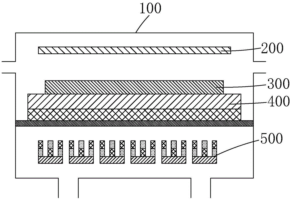
[0045] see Figure 7 , the present invention firstly provides a magnetron sputtering device, comprising a cavity 1, and a partition 20 disposed inside the cavity 1 and connected to the cavity 1, the partition 20 divides the cavity 1 divided into a first chamber 30 and a second chamber 40;

[0046] The first chamber 30 is provided with an anode plate 2, an insulating plate 35 on the separator 20, a back plate 4 on the insulating plate 35, and a back plate 4 on the back plate 4. The target material 3; the second chamber 40 is provided with a magnet group 5, and there is a distance between the magnet group 5 and the separator 20;

[0047] The magnet group 5 includes a magnetic conductor back plate 52 and several magnet units 51 that are spaced ...


PUM


Abstract

The invention provides a magnetron sputtering device and a magnetron sputtering method. A magnet set in the magnetron sputtering device is set to have a plurality of magnet units which are arranged at intervals and distributed in a matrix way, and the S poles and the N poles of the plurality of magnet units in each line and each row of the magnet set are alternatively distributed to form a uniform magnetic filed with matrix periodicity, so that the wear rates of all regions of a target are uniform, target utilization rate is greatly improved, and the film thickness and stress uniformity of film formation are improved; and meanwhile, during magnetron sputtering processing, a motor can drive the whole magnet set to reciprocate in front-back and left-right directions in a horizontal direction, and a plurality of motors can control the plurality of magnet units to respectively move up and down, so that the consumption of the target is more uniform, and the service life of the target is prolonged.

Description

technical field [0001] The invention relates to the field of display technology, in particular to a magnetron sputtering device and a magnetron sputtering method. Background technique [0002] At present, the LCD panel industry mostly uses the magnetron sputtering method for metal film formation. Magnetron sputtering has the advantages of high speed, low temperature, and low damage. Magnetron sputtering introduces a magnetic field on the surface of the target cathode, and uses the magnetic field to confine charged particles to increase the plasma density to increase the sputtering rate. [0003] The working principle of magnetron sputtering is that electrons collide with argon atoms in the process of flying to the substrate under the action of electric field E, so that they are ionized to produce positive argon ions Ar + and new electronic e - ; new electronic e - Fly to the substrate, argon positive ions Ar + Under the action of the electric field E, it accelerates to f...

Claims


Application Information

Patent Timeline
Patent Type & Authority Applications(China)
IPC IPC(8): C23C14/35
CPCC23C14/351
Inventor 王威邓思李娟
Owner WUHAN CHINA STAR OPTOELECTRONICS TECH CO LTD
Why Eureka
Try Eureka