Concrete pile and manufacturing method thereof
A technology of concrete piles and pile tips, which can be applied to sheet pile walls, buildings, and foundation structure engineering, etc. It can solve the problems of poor bearing capacity and small frictional resistance, so as to reduce the amount of concrete, improve bearing capacity, and reduce disturbance effect of effect
- Summary
- Abstract
- Description
- Claims
- Application Information
AI Technical Summary
Problems solved by technology
Method used
Image

Examples
Embodiment 1
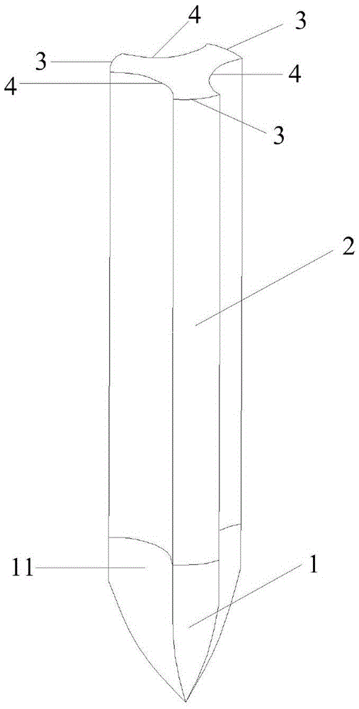
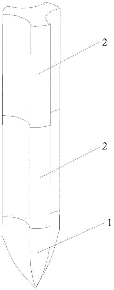
[0056] Such as figure 1 As shown, the present embodiment provides a kind of concrete pile, and this concrete pile comprises:
[0057] The pile tip 1 and the pile body 2, the side projection of the pile tip 1 is conical, and one end of the pile body 2 is connected with the end surface of the pile tip 1;
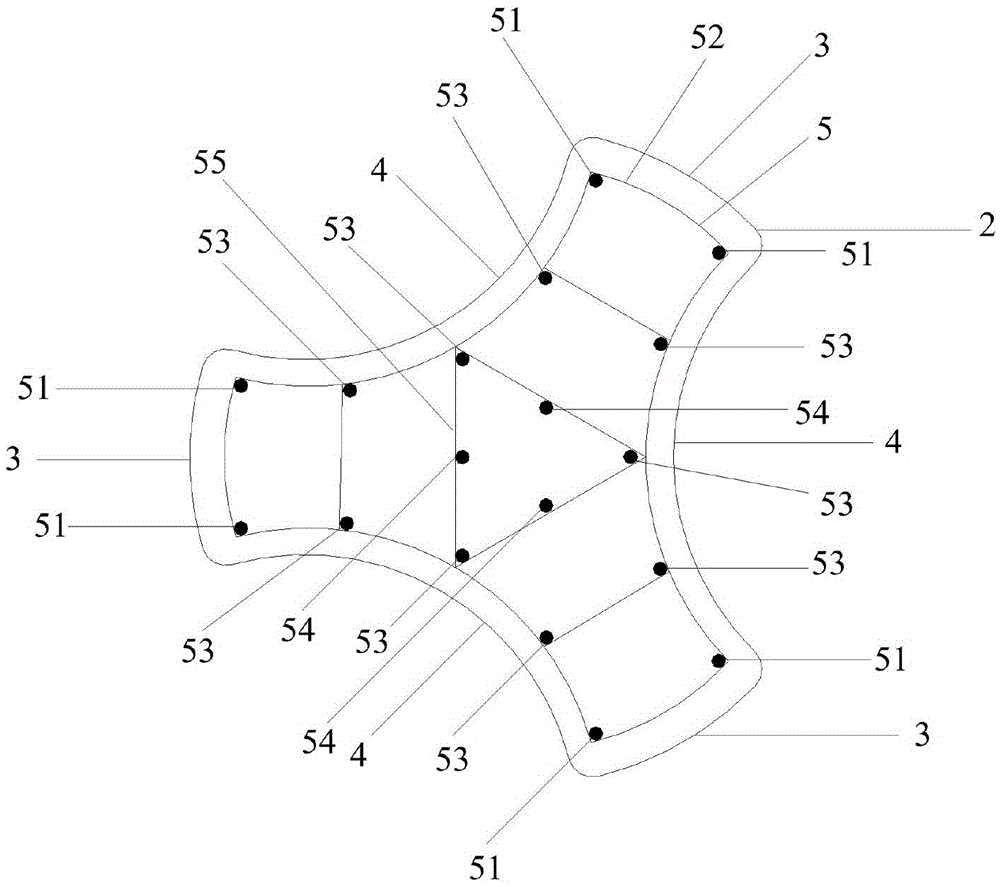
[0058] The side projection of the pile body 2 is a rectangle, and the shape of the cross section of the pile body 2 is herringbone, such as figure 1 shown, and see figure 2 , the shape of the herringbone includes three convex arcs 3 and three concave arcs 4, and the two ends of each convex arc 3 are respectively connected with a concave arc 4 smoothly to form a herringbone. The shape of the end face of the tip 1 is herringbone;
[0059] The end face area of the pile tip 1 is the same as the end face area of the pile body 2 .
[0060]The present invention designs the cross-section of the concrete pile into a herringbone shape, so that the side surface area of the con...
Embodiment 2
[0090] Such as Figure 6 As shown, the embodiment of the present invention provides a method for manufacturing the concrete pile described in the first embodiment. When the concrete pile described in the first embodiment is a prefabricated concrete pile, the method may include:
[0091] Step 101: install the pile formwork with a herringbone cross section, and the shape of the inner cavity of the pile formwork is the same as that of the concrete pile;
[0092] Step 102: pouring concrete into the pile form;
[0093] Step 103: maintaining the concrete in the pile form;
[0094] Step 104: Remove the pile form to obtain concrete piles.
[0095] The present invention designs the cross-section of the concrete pile into a herringbone shape, so that the side surface area of the concrete pile is increased, the friction resistance between the pile side and the soil layer is increased, the bearing capacity of the pile is improved, and the process of foundation treatment is reduced. T...
Embodiment 3
[0106] Such as Figure 9 As shown, the embodiment of the present invention provides a method for manufacturing the concrete pile described in the first embodiment. When the concrete pile described in the first embodiment is a poured concrete pile, the method may include:
[0107] Step 201: sinking a pile form with a spud can with a herringbone cross section into the soil layer, the inner cavity of the spud can has the same shape as the pile point 1 of the concrete pile;
[0108] The spud boot can protect the pile point 1, and at the same time, the spud boot can compact the surrounding soil layer, thereby reinforcing the soil layer around the concrete pile.
[0109] Optionally, a pile form with a spud can and a herringbone cross section can be sunk into the soil layer by means of a vibrating pipe sinking machine.
[0110] Step 202: While pouring concrete into the pile formwork, formwork drafting is performed until the pile formwork is completely pulled out and the spud cans re...
PUM
 Abstract
Description
Claims
Application Information
 - R&D
- Intellectual Property
- Life Sciences
- Materials
- Tech Scout
- Unparalleled Data Quality
- Higher Quality Content
- 60% Fewer Hallucinations
Browse by: Latest US Patents, China's latest patents, Technical Efficacy Thesaurus, Application Domain, Technology Topic, Popular Technical Reports.
© 2025 PatSnap. All rights reserved.Legal|Privacy policy|Modern Slavery Act Transparency Statement|Sitemap|About US| Contact US: help@patsnap.com