
Replaceable beam-column joint earthquake damage control device

A technology for earthquake damage and control devices, which is applied in the direction of earthquake resistance, building components, building structures, etc., can solve the problems that cannot be quickly replaced or repaired, requires high processing technology precision, and consumes a lot of money, and achieves a simple and reliable structure. Effect of quick replacement, reduced vibration response

Active Publication Date: 2016-05-11
INST OF ENG MECHANICS CHINA EARTHQUAKE ADMINISTRATION
View PDF9 Cites 21 Cited by
  • Summary
  • Abstract
  • Description
  • Claims
  • Application Information

AI Technical Summary

Problems solved by technology

[0004] A large number of tests have shown that this type of joint exhibits good ductility under earthquake action, but it also has obvious defects and deficiencies: First, in order to prevent stress concentration at the weakened section, the precision of the processing technology is very high during the construction process. Complex, long construction period, high economic consumption
Therefore, after such joints are subjected to strong earthquakes, plastic hinges are formed at the ends of the beams, with large residual deformations, which cannot achieve the goal of rapid replacement or repair, and further improvement is needed.

Method used


Image

  • Replaceable beam-column joint earthquake damage control device
  • Replaceable beam-column joint earthquake damage control device
  • Replaceable beam-column joint earthquake damage control device

Examples


Embodiment 1

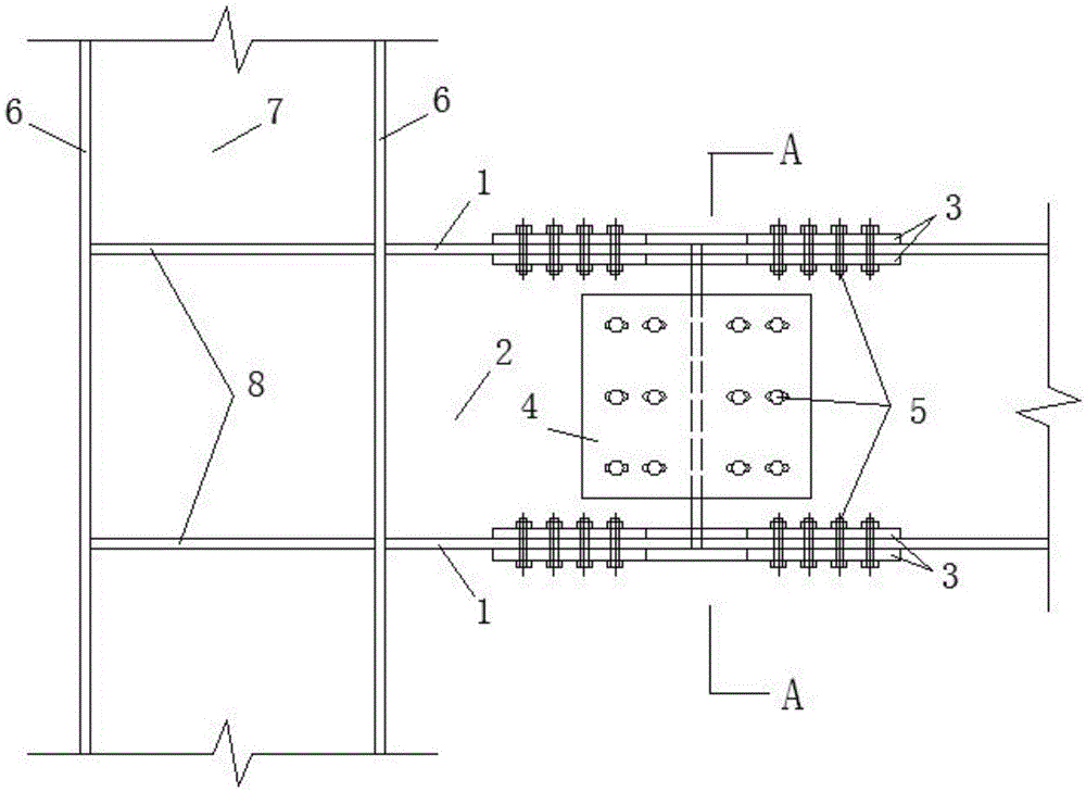
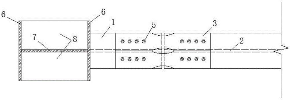
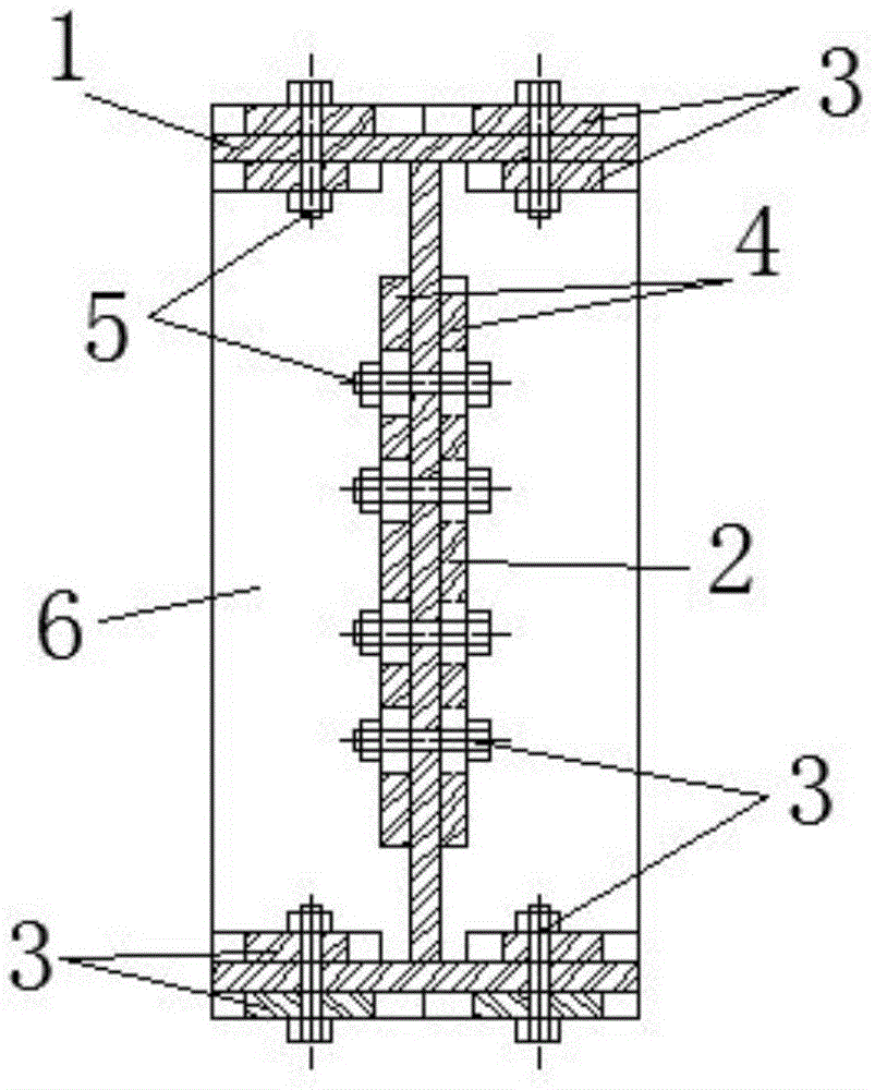
[0021] figure 1 Installation diagram for the replaceable beam-column joint seismic damage control device of the present invention Figure 1 , figure 2 for figure 1 top view of image 3 for figure 1 A-A sectional view, such as Figure 1-Figure 3 As shown, the replaceable seismic damage control device for beam-column joints provided by the present invention includes: a flange energy-dissipating fuse 3, and the flange energy-dissipating fuse 3 is arranged between the connecting gaps of two beam flange plates 1, and the beam flange Flange energy-dissipating fuses 3 are respectively arranged on the upper and lower sides of the plate 1, and bolt holes are arranged on the flange energy-dissipating fuses.

[0022] The present invention can be a beam-column joint of ordinary steel structure or high-strength steel structure, and the flange energy-dissipating fuse 3 is made of ordinary-strength steel or low-yield-point steel, which has good ductility and energy dissipation capacity...

Embodiment 2

[0033] Figure 6 Installation diagram for the replaceable beam-column joint seismic damage control device of the present invention Figure II , On the basis of Embodiment 1, a concrete floor slab 9 is added. The concrete floor slab 9 is poured in situ, and the cooperative work of the two is guaranteed through the shear studs 10 .

[0034] This embodiment is applicable to nodes with floor connections, such as residences. After an earthquake, due to the protection of the cast-in-place concrete slab 9, the energy-dissipating fuse 3 on the upper flange will generally not be damaged, and only the energy-dissipating fuse at the bottom of the beam needs to be replaced.


PUM


Abstract

The invention provides a replaceable beam-column joint earthquake damage control device. The device comprises flange energy consumption fuses which are arranged in connection gaps of beam flange plates arranged in pairs; the upper face and the lower face of each flange plate are both provided with the corresponding flange energy consumption fuse; the flange energy consumption fuses are provided with bolt holes; the flange energy consumption fuses are fixedly connected with beam flanges through friction type high-strength bolts. The replaceable beam-column joint earthquake damage control device is simple and reliable in structure and convenient to install; damage control can be performed on the structure, and connecting joints are protected; vibration energy caused by an earthquake is dissipated, and vibration responses of a building under an earthquake are reduced; replaceability is good, and after an earthquake ends, damaged elements can be fast replaced under the condition that use of the building is not affected.

Description

technical field [0001] The invention relates to the field of anti-seismic technology of structural engineering, in particular to a replaceable seismic damage control device for beam-column joints. Background technique [0002] The steel structure has the characteristics of high strength, light weight, good seismic performance, and short construction period, and is considered to be one of the structural forms with the best seismic performance. With the development of steel structure design, manufacturing and installation technology, its application in engineering practice is becoming more and more extensive. However, a large number of earthquake damage data and experimental studies have shown that: under the action of an earthquake, the stress value at the joints of beams and columns is relatively large, especially the steel near the welding part is prone to brittle fracture, which seriously affects the safety of the structure under the earthquake and causes the building to f...

Claims


Application Information

Patent Timeline
IPC IPC(8): E04B1/98E04B1/58E04B1/24
CPCE04B1/24E04B1/98E04B2001/2406
Inventor 林旭川胡阳阳李吉超
Owner INST OF ENG MECHANICS CHINA EARTHQUAKE ADMINISTRATION
Learn More