
Rolling contact fatigue testing machine

A technology of rolling contact fatigue and testing machine, which is applied in the direction of mechanical bearing testing, etc. It can solve the problems of unsuitable fatigue performance state, unsuitable for rolling contact fatigue failure, unable to quickly evaluate and select, etc., and achieve the effect of direct structure and high efficiency

Inactive Publication Date: 2016-05-11
SHANGHAI JIAO TONG UNIV
View PDF6 Cites 4 Cited by
  • Summary
  • Abstract
  • Description
  • Claims
  • Application Information

AI Technical Summary

Problems solved by technology

For example: "A Rolling Contact Fatigue Tester" (see Chinese Invention Patent, Publication No. CN102494963A), which involves a fatigue test device that is only suitable for the contact of a single roller element, and a pair of idler wheels provide driving force and loading; " Working Condition Simulated Rolling Contact Fatigue Tester" (see Chinese Invention Patent, Publication No. CN1715869A), relates to a fatigue test device only suitable for ball-plane rolling contact, which is not suitable for evaluating rolling contact fatigue failure under plane strain ; "A Bearing Roller Contact Fatigue Tester and Operation Method" (see Chinese Invention Patent, Publication No. CN102147341A), relates to a fatigue test device suitable for rolling contact of roller elements with convexity characteristics, which is not suitable for Evaluation of Rolling Contact Fatigue Performance State on General Finished Cylindrical Surfaces
In addition, neither of the above two devices can quickly evaluate and select the cutting conditions that produce rolling surfaces through rolling contact fatigue performance experiments.

Method used


Image

  • Rolling contact fatigue testing machine

Examples


Embodiment

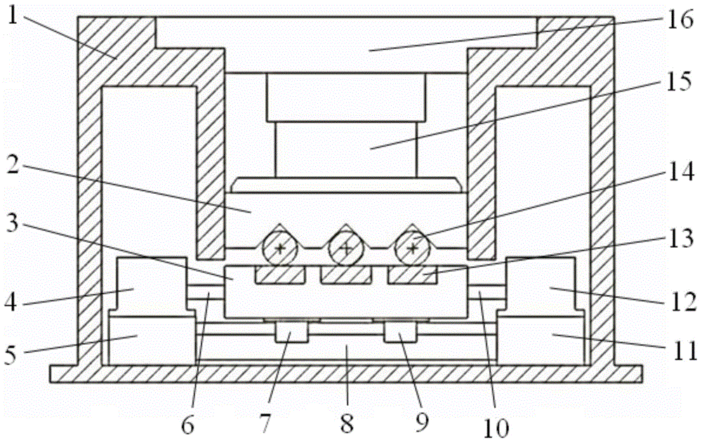
[0027] A rolling contact fatigue testing machine whose structure is as follows figure 1 As shown, it mainly includes a frame body 1, a loading platform 2, a sliding platform 3, a linear motor 4, a linear guide 8, a linear motor 12, a loading mechanism 15, a loading mechanism 16, and the like. The frame body 1 mainly plays the role of stability and structural support. It wraps other parts of the experimental machine inside. Due to the force and vibration, it should be firmly connected to the desktop during use. The bottom of the frame body 1 is horizontally fixed with a linear guide 8 and a matching sliding block 7, a sliding block 9; the sliding platform 3 is fixed on the sliding block 7, the sliding block 9 and slides horizontally along the linear guide 8; the sliding block 7, the sliding block 9 Via the connecting rod 6, the connecting rod 10 is connected with the linear motor 4 and the linear motor 12. The linear motor 4 and the linear motor 12 are respectively fixed on the...


PUM


Abstract

The invention relates to a rolling contact fatigue testing machine, and the machine is mainly used to carry out rapid fatigue test on rolling contact in the plane strain state. The fatigue testing machine can effectively simulate fatigue of a component with plane-strain rolling contact feature and evaluate and select processing parameters for forming the rolling contact surface, and is thus an ideal testing machine to research on the surface fatigue failure mechanism of materials. The fatigue testing machine is composed of a frame body, a linear guide rail, a sliding platform, linear motors, a loading platform and a loading mechanism, multiple strip-shaped samples can be placed on the sliding platform on the linear guide rail, and one or multiple cylindrical rolling bodies is / are arranged in the lower portion of the loading platform correspondingly. During test, the loading mechanism enables the samples make contact with the rolling bodies in certain pressure, the linear motors drive the sliding platform to make reciprocating movement in certain amplitude, and the fatigue condition of the samples can be observed after certain period.

Description

technical field [0001] The invention relates to a fatigue test device, in particular to a rolling contact fatigue test machine. Background technique [0002] Cylindrical roller bearing is a kind of bearing widely used in various mechanical equipment. The rolling elements are cylindrical rollers, and the contact type with the raceway is line contact. [0003] In the process of bearing use, normal fatigue failure is inevitable. Therefore, the law between the fatigue life of the bearing and the material and working conditions is studied, the ideal design scheme is found, and the mechanism of fatigue failure on the surface of the material is further studied. The optimal design of the bearing is very important, and the fatigue experiment is a very effective experimental research method. [0004] Through the retrieval of existing patents, it is found that among the contact type fatigue testing machines, there is no more targeted and more efficient fatigue testing method or equip...

Claims


Application Information

Patent Timeline
IPC IPC(8): G01M13/04
Inventor 张雪萍王晓骎
Owner SHANGHAI JIAO TONG UNIV
Learn More