Liquid crystal lens imaging method

A technology of liquid crystal lens and imaging method, which is applied in the direction of instruments, nonlinear optics, optics, etc., and can solve the problems of incompletely consistent polarized light propagation behavior, increasing the production cost of liquid crystal lenses, adding liquid crystal lenses or liquid crystal layers, etc.

Active Publication Date: 2020-06-23
SUPERD CO LTD
View PDF6 Cites 0 Cited by
  • Summary
  • Abstract
  • Description
  • Claims
  • Application Information

AI Technical Summary

Problems solved by technology

[0004] (1) The multi-liquid crystal lens superposition scheme or the multi-liquid crystal layer superposition scheme greatly increases the production cost of the liquid crystal lens due to the increase in the number of liquid crystal lenses or liquid crystal layers
[0005] (2) Due to the increase in the number of liquid crystal lenses or liquid crystal layers, the thickness of the device is also greatly increased, making it difficult for liquid crystal lens imaging devices to be installed in mobile devices
[0006] (3) Due to the different positions of the liquid crystal lenses or liquid crystal layers in the system, the propagation behavior of the two components of polarized light is not completely consistent, which reduces the imaging quality of the system
[0007] (4) Using the above scheme for image processing is a purely digital arithmetic operation, which is only applicable to the image part in the linear response range of the image sensor, and not applicable to the part of the image in the nonlinear response range

Method used


Image

  • Liquid crystal lens imaging method
  • Liquid crystal lens imaging method
  • Liquid crystal lens imaging method

Examples


Embodiment Construction

[0027] In order to understand the above-mentioned purpose, features and advantages of the present invention more clearly, the present invention will be further described in detail below in conjunction with the accompanying drawings and specific embodiments. It should be noted that, in the case of no conflict, the embodiments of the present application and the features in the embodiments can be combined with each other.

[0028] In the following description, many specific details are set forth in order to fully understand the present invention, but the present invention can also be implemented in other ways different from those described here, therefore, the present invention is not limited to the specific embodiments disclosed below limit.

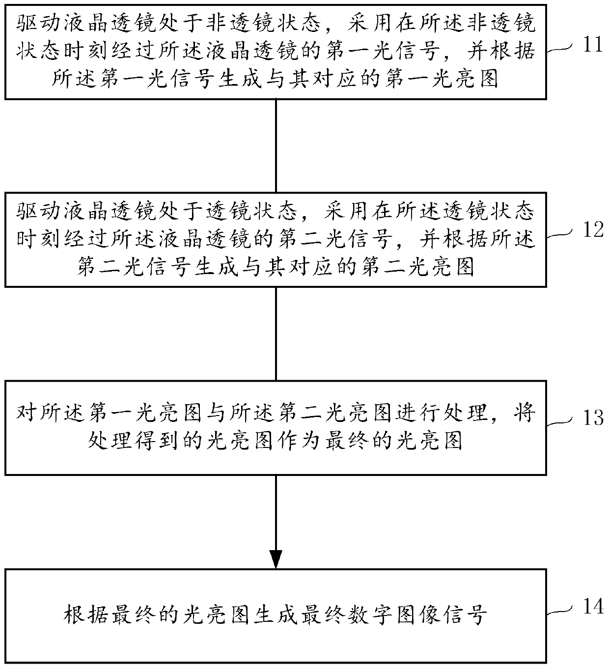
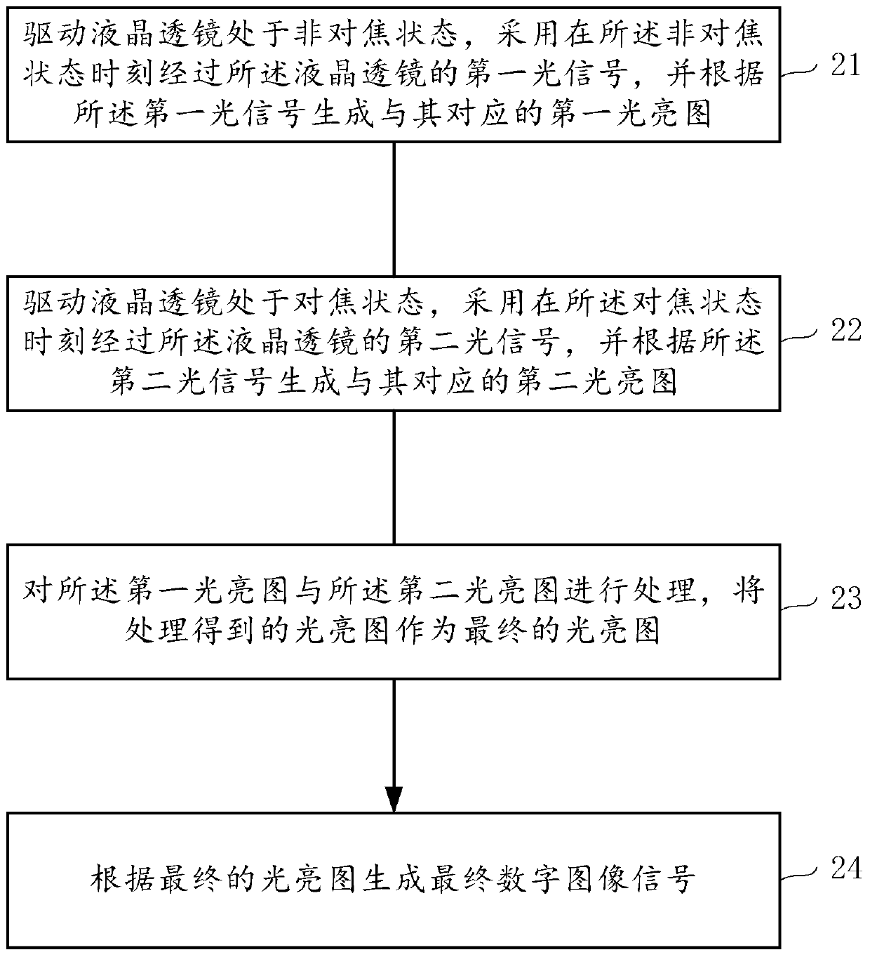
[0029] The liquid crystal lens imaging method provided by the invention comprises the following steps:

[0030] Driving the liquid crystal lens to be in the first state, adopting the first light signal passing through the liquid crystal l...


PUM


Abstract

The invention provides a liquid crystal lens imaging method, comprising: driving a liquid crystal lens to be in a first state, using a first optical signal which passes through the liquid crystal lens at the moment of the first state, generating a first lighting graph corresponding to the first optical signal according to the first optical signal; driving the liquid crystal lens to be in a second state, using a second optical signal which passes through the liquid crystal lens at the moment of the second state, generating a second lighting graph corresponding to the second optical signal according to the second optical signal; processing the first lighting graph and the second lighting graph, using the lighting graph obtained by processing as a final lighting graph; and according to the final lighting graph, generating a final digital image signal. Through processing the lighting graphs, the liquid crystal lens imaging method finally obtains the digital image signal, so as to prevent error problems caused by calculation just aimed at the linear response interval of an imaging sensor when the digital image signal is directly used for processing. Thus, a calculation result of the lighting graph is improved.

Description

technical field [0001] The invention relates to the technical field of lens imaging, in particular to a liquid crystal lens imaging method. Background technique [0002] Due to the anisotropy of liquid crystal materials, liquid crystal devices usually only correspond to polarized light; when liquid crystal lenses are used in imaging equipment, polarizing devices, such as polarizers, are required to make the incident light linearly polarized. However, the use of polarizers reduces the light intensity to less than half of the original intensity value. In this way, in a darker environment, the amount of light reaching the image sensor may be insufficient, causing a decrease in the signal-to-noise ratio and lowering the imaging quality. [0003] In order to avoid the use of polarizers, in the imaging system, a plurality of liquid crystal lenses whose initial alignments of the liquid crystal layers are perpendicular to each other can be stacked to form a liquid crystal lens, or ...

Claims


Application Information

Patent Timeline
Patent Type & Authority Patents(China)
IPC IPC(8): G02F1/29
Inventor 郁树达叶茂包瑞崔春晖
Owner SUPERD CO LTD
Why Eureka
Try Eureka