Computer-implemented method for simulation of entire electronic circuit

A circuit and sub-circuit technology, applied in the field of computer implementation for simulating the total circuit, can solve problems such as time-consuming, unstable display, and failure to realize the switch state, and achieve the effect of improving calculation results

Pending Publication Date: 2018-12-28
디스페이스게엠베하
View PDF0 Cites 0 Cited by
  • Summary
  • Abstract
  • Description
  • Claims
  • Application Information

AI Technical Summary

Problems solved by technology

This approach is extremely time-consuming, requires considerable expertise, and does not necessarily lead to a stable simulation, since in the test runs of the simulations used to assess the stability no possible specific switching states w

Method used


Image

  • Computer-implemented method for simulation of entire electronic circuit
  • Computer-implemented method for simulation of entire electronic circuit
  • Computer-implemented method for simulation of entire electronic circuit

Examples


Embodiment Construction

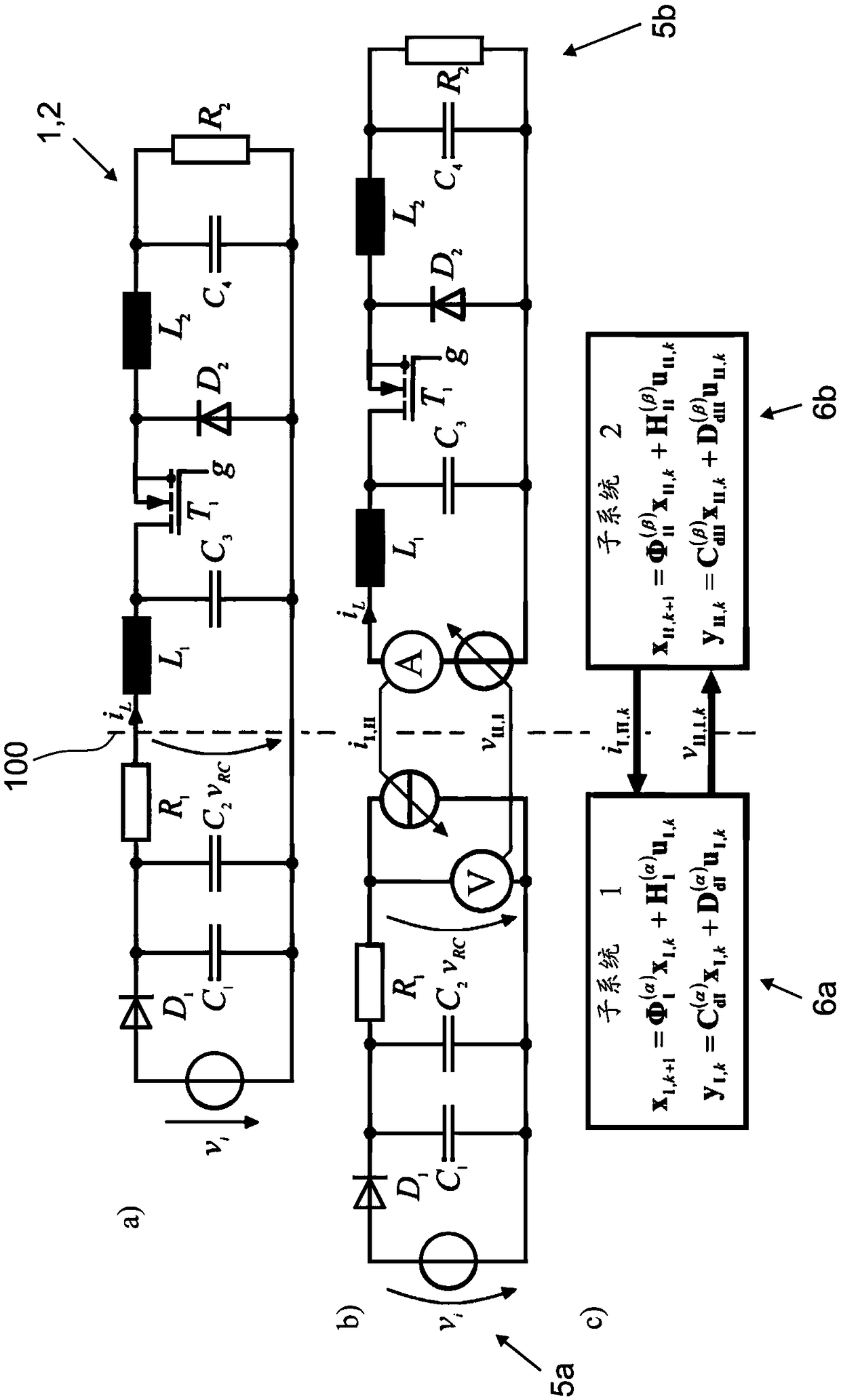
[0045] exist Figures 1 to 10 A computer-implemented method 1 for simulating a total circuit 2 with circuit elements (R, L, C, D, T) is shown with different emphasis in .

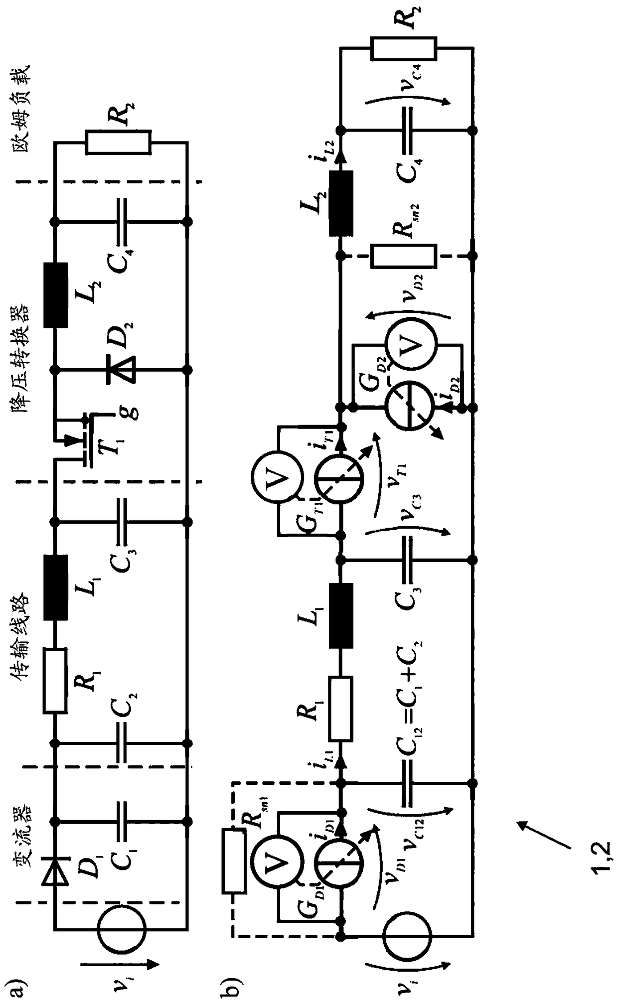
[0046] figure 1 The exemplary total circuit 2 in a includes a converter (Rectifier), a transmission line (Transmission line), a step-down converter (Buck converter) and an ohmic load (Load) from left to right. The semiconductor switch is a diode D 1 、D 2 and MOSFET transistor T 1 .

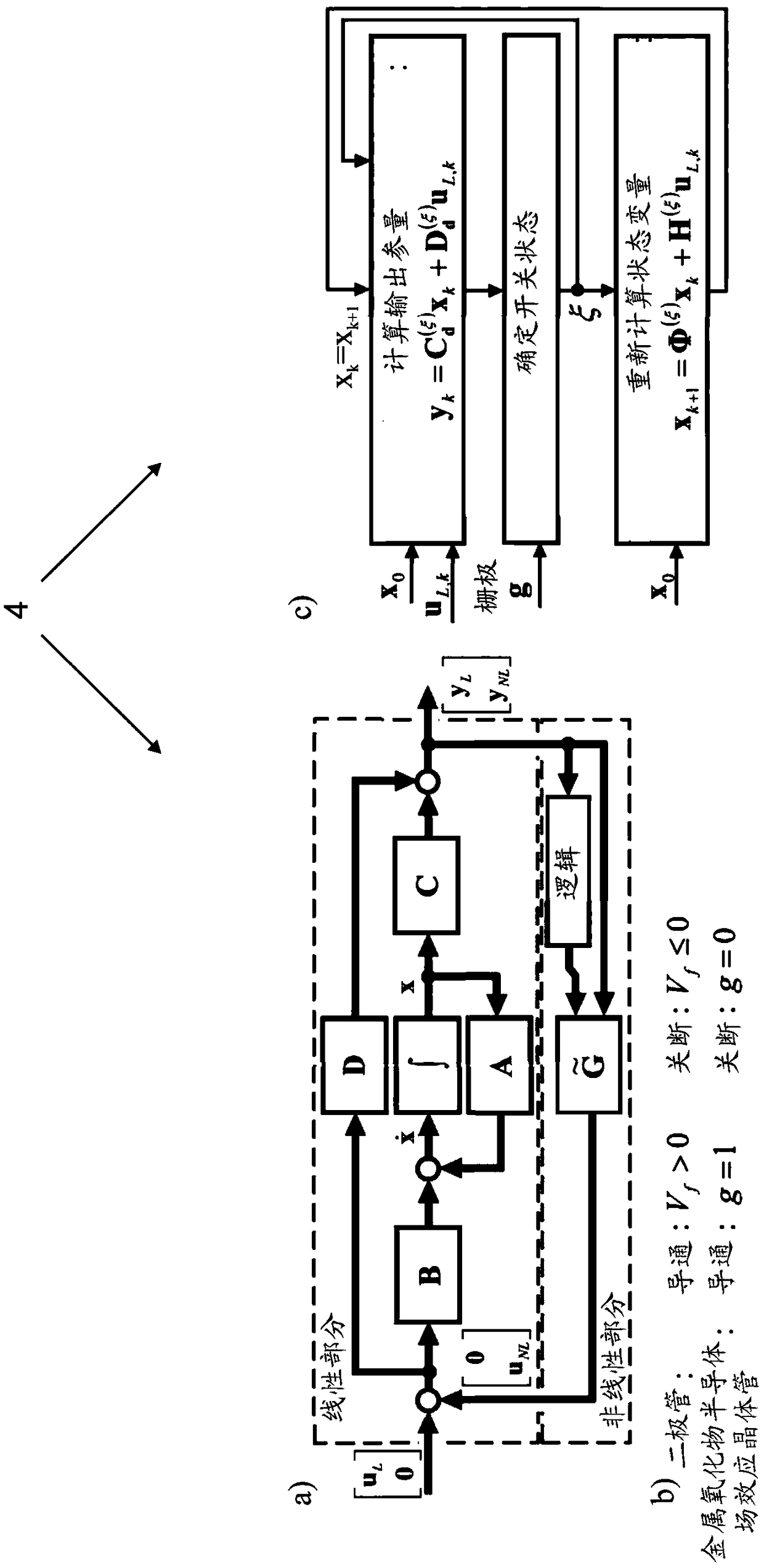
[0047] figure 1 b shows the transformation of the overall circuit 2 into a suitable representation for expressing the overall circuit 2 in the state space. semiconductor switch D 1 、D 2 , T 1 Here by having conductance G, G D1 , G D2 , G T1 A voltage-controlled current source is depicted. conductance G according to the semiconductor switch D 1 、D 2 , T 1 The switching state of the change, so that in the state space representation according to the semiconductor switch D 1 、D 2 , T 1 The switching states of the...


PUM


Abstract

A computer-implemented method for simulation of an electrical circuit with circuit components by at least one computing unit includes mapping a coupling of the substrate representations in a couplingequation system for exchange of calculated coupling variables between the subcircuits. The method also includes calculating, in an evaluation step, at least one stability parameter on a basis of the coupling equation system, and deciding, in a selection step and depending on the at least one calculated stability parameter, whether the current separation of the electrical circuit into subcircuits will be used as the basis of the simulation. The method further includes performing, after a successful selection, the simulation of the electrical circuit by calculating the substrate space representations on the at least one computing unit.

Description

technical field [0001] The invention relates to a computer-implemented method for simulating a total circuit with circuit elements and which is mathematically described by a total state-space representation by means of at least one calculation unit, the total circuit In the separation step, the circuit is decomposed into at least two subcircuits by separating the circuit branches, wherein each subcircuit is described mathematically by a substate space representation, wherein the substate space represents the coupling via the separated circuit branches The variables are coupled to each other, and each subcircuit is computed by numerically solving the coupled substate space representation on at least one computational unit. Background technique [0002] The invention relates to the technical field of simulating circuits in real time in order to influence or test technical physical processes. Technical physical processes may involve, for example—in particular in automation tec...

Claims


Application Information

Patent Timeline
IPC IPC(8): G06F17/50
CPCG06F30/30G05B13/04G05B17/02G06F2111/10G06F2119/06G06F30/367G06F30/20
Inventor A·基弗K·威廷F·普施曼
Owner 디스페이스게엠베하
Why Eureka
Try Eureka