Platform camera for aircraft and aircraft using same

A technology for a pan-tilt camera and an aircraft, which is applied in the field of aircraft, can solve the problems of cumbersome adjustment process and increase the difficulty of use, and achieve the effects of simple adjustment process, convenient operation and reduced difficulty in use.

Active Publication Date: 2016-05-11
POWERVISION ROBOT INC
View PDF9 Cites 4 Cited by
  • Summary
  • Abstract
  • Description
  • Claims
  • Application Information

AI Technical Summary

Problems solved by technology

No matter which one, the adjustment process is mor

Method used


Image

  • Platform camera for aircraft and aircraft using same
  • Platform camera for aircraft and aircraft using same
  • Platform camera for aircraft and aircraft using same

Examples


Example Embodiment

[0069] Embodiment one

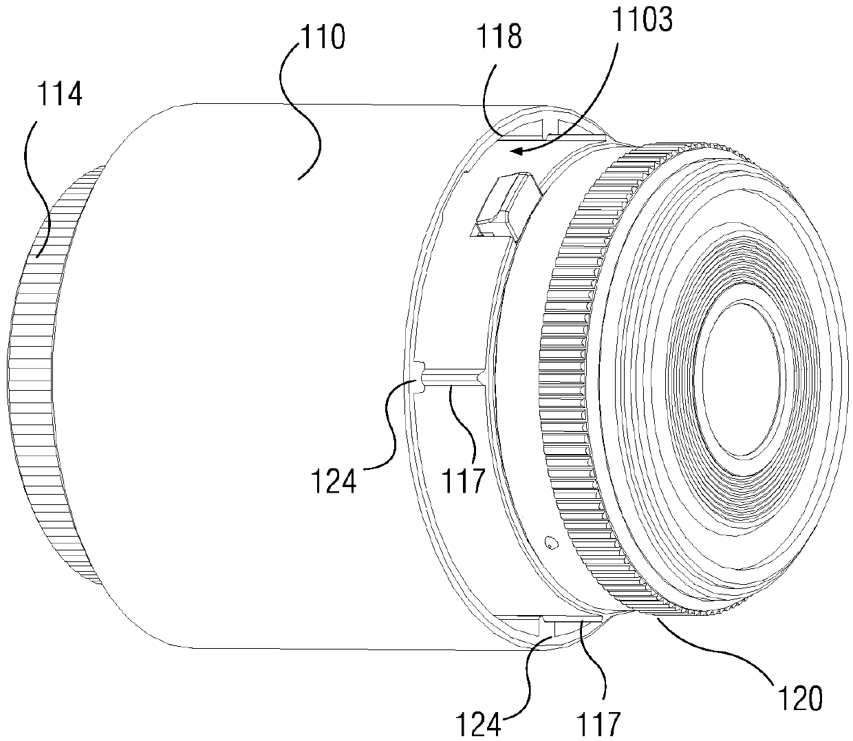
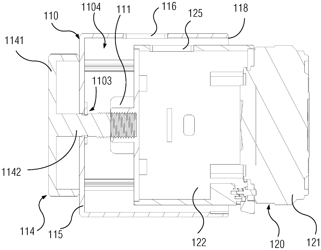
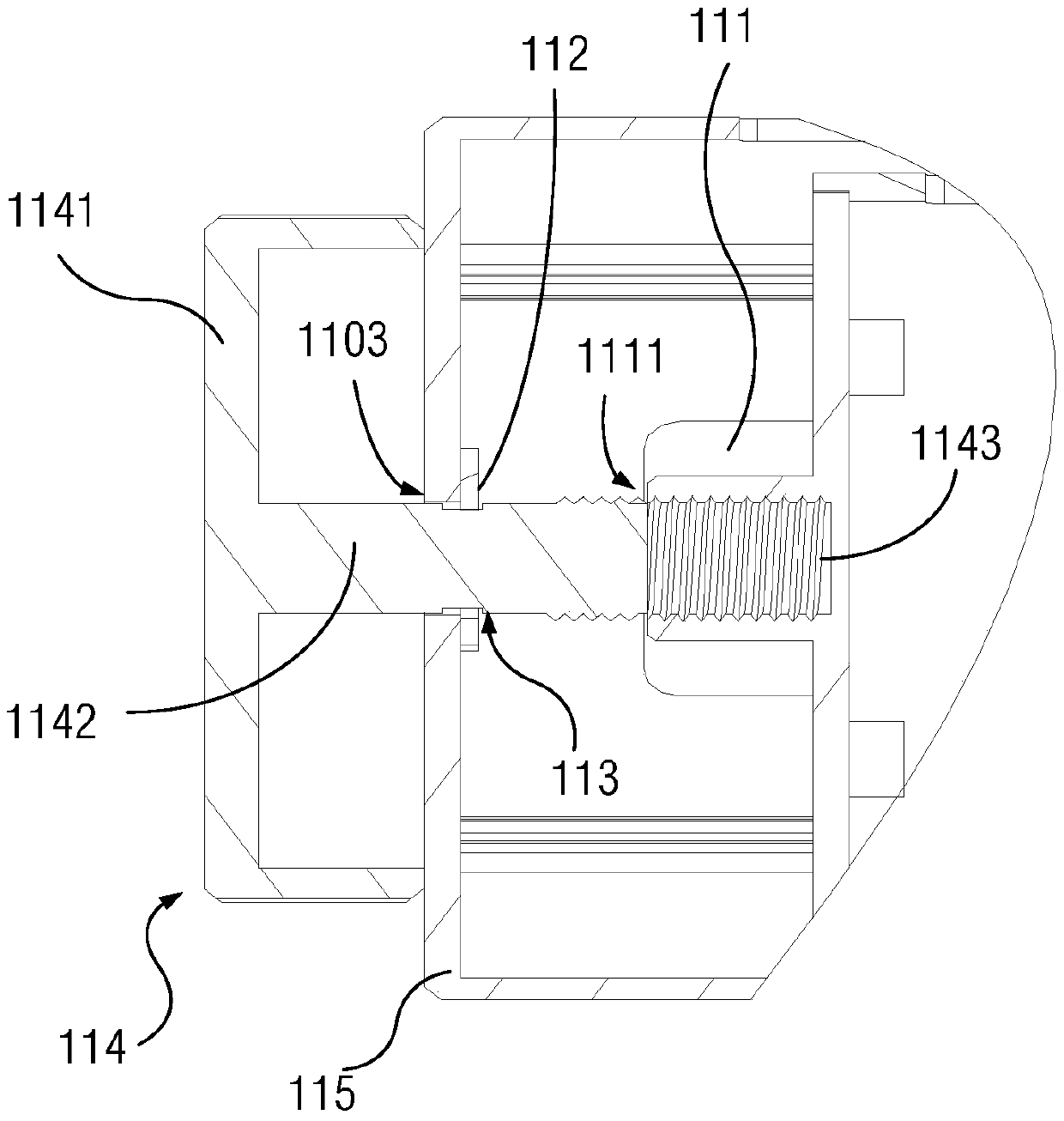
[0070] In order to solve the technical defect of the cumbersome center of gravity leveling operation of the pan-tilt camera of the aircraft in the prior art, the embodiment of the present invention provides a pan-tilt camera of the aircraft, such as figure 1 shown.

[0071] The aircraft is equipped with a propeller to drive the flight of the aircraft. One end of the aircraft in the first direction has a gimbal, and the gimbal camera is mounted on the gimbal. The first direction mentioned here may be parallel or substantially parallel to the direction of gravity that the aircraft bears when it is in flight. Moreover, the gimbal and the propeller described here can be any structure that can install the gimbal camera and drive the aircraft to fly. No matter what structure the gimbal and propeller adopt, the gimbal camera in this embodiment is applicable.

[0072] See at figure 1 simultaneous combination of figure 2 and image 3 , the pan-tilt camera...

Example Embodiment

[0095] Embodiment two

[0096] In order to solve the technical defect of the cumbersome center of gravity leveling operation of the pan-tilt camera of the aircraft in the prior art, Embodiment 2 of the present invention provides a pan-tilt camera of the aircraft, such as Figure 4 shown.

[0097] The aircraft is equipped with a propeller to drive the flight of the aircraft. One end of the aircraft in the first direction has a gimbal, and the gimbal camera is mounted on the gimbal. The first direction mentioned here may be parallel or substantially parallel to the direction of gravity that the aircraft bears when it is in flight. Moreover, the gimbal and the propeller described here can be any structure that can install the gimbal camera and drive the aircraft to fly. No matter what structure the gimbal and propeller adopt, the gimbal camera in this embodiment is applicable.

[0098] see Figure 4 and Figure 5 , the pan-tilt camera of the present embodiment includes:

[...


PUM


Abstract

The invention discloses a platform camera for an aircraft. The platform camera is installed on a platform positioned at one end of the aircraft in a first direction. The platform camera comprises a camera shell, an imaging module and a rotary knob, wherein the camera shell is connected to the platform in the first direction, and a cavity is formed inside the camera shell; the imaging module is arranged in the cavity; the rotary knob is connected to the imaging module through a transmission mechanism, and the transmission mechanism is configured to drive the imaging module to move in a second direction by using the rotation of the rotary knob. According to the platform camera disclosed by the invention, the imaging module moves in the second direction by manually rotating the rotary knob, and then the center-of-gravity position of the imaging module can be adjusted, so that the operation is convenient, the adjustment process is simple, and the using difficulty is reduced.

Description

technical field [0001] The invention relates to the technical field of aircraft equipment, in particular to a pan-tilt camera of an aircraft and an aircraft using the same. Background technique [0002] At present, aircraft or unmanned aerial vehicles have been more and more widely used in social life. Through wireless remote control, close-range observation of places that are difficult for people to reach, or high-altitude aerial photography, thus providing convenience for observation and shooting. [0003] In the prior art, the gimbal is generally installed at the nose of the aircraft through a bracket, and the gimbal camera is fixed on the gimbal to realize the shooting of the gimbal camera when the aircraft is flying. In order to avoid tilting of the gimbal camera relative to the center of gravity of the aircraft and affect the shooting quality, and to ensure the stability of the gimbal camera during shooting, the center of gravity of the gimbal camera needs to be adjust...

Claims


Application Information

Patent Timeline
IPC IPC(8): G03B17/56B64D47/08G03B30/00
CPCG03B17/566B64D47/08G03B17/56
Inventor 郑卫锋其他发明人请求不公开姓名
Owner POWERVISION ROBOT INC
Why Eureka
Try Eureka