
Method for improving uniformity of ion beams of large-parameter ion source

An ion source, uniformity technology, applied in the direction of discharge tubes, electrical components, circuits, etc., can solve the problems of reducing the efficiency of the ion source, long cycle, difficulty and so on, and achieve the effect of improving beam uniformity

Active Publication Date: 2016-05-11
48TH RES INST OF CHINA ELECTRONICS TECH GROUP CORP
View PDF4 Cites 4 Cited by
  • Summary
  • Abstract
  • Description
  • Claims
  • Application Information

AI Technical Summary

Problems solved by technology

[0005] Every time an improvement is made, a comprehensive test of the beam uniformity of the ion source is required, which significantly increases the cycle and cost of ion source development
Moreover, with the increase of the ion source diameter, this improvement will be more complicated, the interaction of various factors will be more obvious, and the cost and cycle cannot be effectively controlled
[0006] To sum up, the traditional technical means to improve beam uniformity by changing the discharge chamber structure and magnetic field not only has high cost and long cycle, but also tends to reduce the efficiency of the ion source when improving beam uniformity.
As the diameter of the ion source increases, this method of improving the structure of the discharge chamber and the magnetic field is more difficult

Method used


Image

  • Method for improving uniformity of ion beams of large-parameter ion source
  • Method for improving uniformity of ion beams of large-parameter ion source
  • Method for improving uniformity of ion beams of large-parameter ion source

Examples


Embodiment Construction

[0022] The present invention will be further described in detail below with reference to the drawings and specific embodiments of the specification.

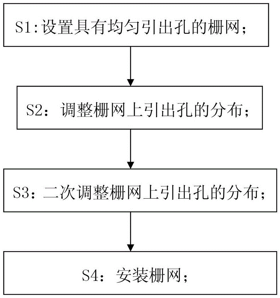
[0023] Such as figure 1 As shown, the method for improving the uniformity of ion beam current of a large-aperture ion source of the present invention includes the following steps:

[0024] S1: Set up a grid with lead holes;

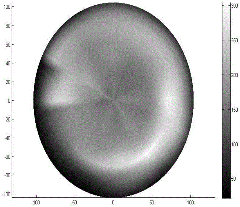
[0025] A grid with evenly distributed extraction holes is used and installed at the beam outlet position of the ion source discharge chamber. Test the beam density uniformity and draw the beam density distribution diagram A.

[0026] S2: Adjust the distribution of lead holes on the grid;

[0027] According to the beam density distribution diagram A, adjust the distribution of the lead-out holes on the grid. The lead-out holes should be appropriately reduced in the positions with high beam current density, and the lead-out holes should be appropriately increased in the positions with high beam current density.

[0028...


PUM


Abstract

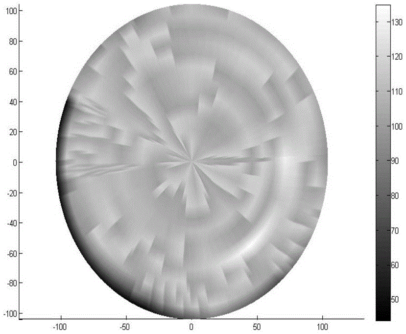
The invention discloses a method for improving uniformity of ion beams of a large-parameter ion source. The method comprises steps of S1: arranging a grid net with lead-out holes, installing the grid net in a beam outlet position of an ion source discharge chamber, testing uniformity of beam density and drawing a beam density distribution graph A; S2: adjusting distribution of the lead-out holes in the grid net, adjusting distribution of the lead-out holes in the grid net according to the beam density distribution graph A, installing the grid net with adjusted lead-out holes in the same beam outlet position of the same ion source discharge chamber, testing uniformity of the beam density and then drawing a beam density distribution graph B; S3: adjusting the distribution of the lead-out holes in the grid net for the second time, and according to the beam density distribution graph B, finely adjusting the distribution of the lead-out holes in the grid net; and S4: installing the grid net: the final grid net is installed so that uniformity of the ion beams of the ion source can satisfy requirements. The method is advantaged by simple principles, simple operation and capability to reduce cost.

Description

Technical field [0001] The present invention mainly relates to the field of semiconductor manufacturing, and specifically refers to a method for improving the uniformity of ion beam current of a large-caliber ion source. Background technique [0002] As the size of substrates in the semiconductor manufacturing industry and other industries continues to increase, the size of the equipment required is also increasing. The ion source is a key component in equipment such as ion beam etching machines, and its caliber is also increasing, and the requirements for the uniformity of ion beam current are also increasing. [0003] In order to meet this ever-increasing requirement, uniform field sources, divergent field sources, radial field sources, angled field sources and multi-pole field sources have appeared successively. Among them, the beam density of the multi-pole field source has better uniformity, but its obvious disadvantages are low efficiency and complex structure. These are al...

Claims


Application Information

Patent Timeline
IPC IPC(8): H01J37/02H01J37/04H01J37/317
CPCH01J37/02H01J37/04H01J37/317H01J2237/02
Inventor 张赛佘鹏程陈特超陈庆广
Owner 48TH RES INST OF CHINA ELECTRONICS TECH GROUP CORP
Learn More